Showing posts with label mods. Show all posts

Wednesday, October 21, 2009

Epiphone Valve Junior - the Gain Matrix Mod Part II


I'm going to start describing the Valve Junior Gain Matrix Mod with the physical side of the job. There are three gain stages in the Valve Junior. I'm installing one switch for each of these stages. Here's the chassis marked out for drilling the switch holes:


Valve Junior Gain Reduction Mod - chassis marked for drilling


The switches will change the gain and frequency response by selecting and disconnecting the cathode bypass capacitors. Here is a front of chassis view the three switches installed:


Valve Junior Gain Reduction Mod - switches installed


And here they are from inside the chassis:


Valve Junior Gain Reduction Mod - switches from inside chassis


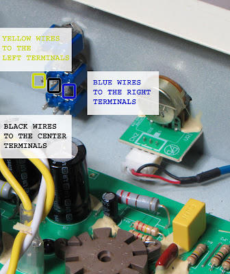
In the following post you'll see that the wires are color coded the wires to make it a bit easier to follow the wiring.
The yellow wires are for the "stock" configuration for each stage.
They connect to the left hand terminal of their respective switch.
The blue wires are for the "mod" value caps.
They connect to the right hand terminals.
The black wires are for ground and they connect to the center terminals:


Valve Junior Gain Reduction Mod - wire color coding


Next up I'll show the actual circuit wiring and in the fourth I'll draw up a schematic for the mod.


Tuesday, October 20, 2009

Champion 600 Speaker Upgrade Comparison


I installed four different speakers in my Champion 600 and ran some frequency response sweeps for the sake of comparison.*

What I saw in the graphs pretty much confirmed what I heard in each of them.

First the stock speaker compared to a Jensen Mod:


Champion 600 Stock Speaker vs Jensen Mod


Just as my ear was telling me - the Jensen is a touch more efficient and a touch smoother but they really didn't sound all that different. I found the difference to be hardly worth the upgrade cost.

Here is the Weber alnico with a late breakup cone compared to the stock Champion 600 speaker:


Champion 600 stock speaker vs Weber alnico late break up ribbed cone


Notice that the Weber late breakup alnico is a good bit more efficient than the stock speaker up to about 3K, where it drops off dramatically. This probably accounts for some people experiencing the Weber as dark sounding. What isn't evident from the graph is that in addition to the increased bass response the Weber is more able to handle the bass so it doesn't fart out the way the stock speaker does.

The next graph is interesting. It compares the Weber late break up ribbed cone to the Weber early break up smooth cone:


Weber alnico speaker comparison - late break up ribbed cone vs early break up smooth cone


They're pretty similar in the bass but in the upper mids and treble they're very different. So in addition to the breakup characteristics they have quite different upper range response. Personally I prefer the smooth cone sound - it sounds a bit more vintage to my ear. The ribbed cone sounds tighter and more modern. They both sound great though and are both worth the upgrade.

Here is the smooth cone Weber compared to the stock speaker:


Weber smooth cone early break up alnico compared to the Fender Champion 600 stock speaker


It look much more like the original in the treble response. Kind of like the stock speaker with increased bass and mids (and better bass handling).


Here's plots for all four speakers on the same graph - just for ease of comparison:


Frequency response of all four Champion 600 speakers


Incidentally, I found that the stock grill cloth really does flap around at higher volumes making some nasty farting and flapping along with the low notes. I cut mine out when I cut down the baffleboard for the Weber speaker installation and am looking for something to replace it with.


* These graphs are for the sake of comparison between the speakers. Since they aren't anechoic chamber tests the graphs include the room effects so don't pay to much attention to each tiny peak and dip. They don't show isolated speaker response but work fine to illustrate how the speakers differ from each other under the same room conditions.


Thursday, March 19, 2009

Fender Champion 600 hum reduction mod


The Champion 600 I've been working on came back in with a request for the cathode referenced heater mod to reduce the hum. For a single ended amp this particular one is actually pretty quiet already. It certainly hums less than any of the vintage Champs I've seen. I don't mind a little bit of hum myself but the owner is new to tube amps so he's a bit more sensitive to it than I am. The mod is a real simple one though so I thought I'd take a crack at it and see if it did anything.


R15 and R16 are the resistors that reference the heater filaments to ground. A old trick for single ended amps is to move the end of these resistors to the cathode of the output tube.

Since I've moved the cathode bypass cap as part of another mod, I had a convenient place to connect the resistors. If the cap is still there the resistors could be connected to the top of R10 instead (indicated by the red circle).


Here's a measurement taken off the output with a 4 ohm dummy load connected:


You'll notice that there's almost no reduction in the fundamental or even any of the lower harmonics. It's not until about 2K Hz that we start to see a reduction in the hum. As I mentioned earlier, this amp was pretty quiet to begin with. Curiously the owner actually perceived it as humming slightly more with the mod installed so I'm going to put it back to stock when it comes back in to get a Weber Alnico speaker put in.

Thursday, February 26, 2009

Fedner Champion 600 12DW7 / ECC832 Mod Part 1 - Update


I'm focusing here on the 12DW7 / ECC832 partly out of curiosity and partly because it's half the work to rebias for the new tube. What is a 12DW7? Technical details can be found in the 12DW7 mod part 2.

The goal of the mod is to get a good bedroom level clean sound with a more useful range in the volume control. You can lower the gain and get more headroom by substituting a 12AT7,12AY7 or 12AU7 for the 12AX7. It won't be biased properly, but you may like the sound anyway and you're not going to hurt anything.

You can also plug a 12DW7/ECC832 in place of a 12AX7. A 12DW7 / ECC832 is one half 12AX7 and one half 12AU7. If you like the sound, try this mod to bias the lower mu half of the tube correctly.

THE UBIQUITOUS DISCLAIMER: AKAVALVE ASSUMES NO RESPONSIBILITY FOR THE SAFETY OF ANYONE IMPLEMENTING THESE INSTRUCTIONS. IF YOU ARE NOT FAMILIAR WITH SAFE PRACTICE IN HIGH VOLTAGE CIRCUITS, DO NOT ATTEMPT THIS YOURSELF.

All it takes is a 12K resistor jumpered in parallel with the stock 100K plate resistor R8 and a 1K resistor in parallel with the 1.5K cathode resistor R2. They're the two dark brown 3 watt IRC resistors shown in the middle of the picture.


The effect of putting 2 resistors in parallel is to reduce the overall resistance:


So the stock plate resistor in parallel with the additional 12K one gives a combined value of 10.7K for the plate. This greatly increases the current through the tube, which is what we need for a 12AU7.

With the current increased we need to change the bias of the stage to suit a 12AU7. With the stock resistor it will be running quite cold. The added 1K resistor in parallel with the stock 1.5K one yields a total resistance of 600 ohms.

If you're interested, the working through of the parallel resistance formula is covered in more depth in the Fat Boost Resistor Value post.


Here's a close up of the plate resistor. This jumpering method makes it very easy to remove the mod if you decide to go back to stock.


You can see below that the joint on the left hand of the plate resistor is not perfect - the solder hasn't flowed onto the lead of the original as completely as one would like. This is just for a listening test though so I didn't bother touching it up.


With this mod in place the amp is much cleaner and much quieter. It's important to note that you should NOT plug a 12AX7 back into the socket with the mod in place. A 12AX7 triode can't handle the amount of current that a 12AU7 triode can, so half of your 12AX7 will be toasted by the rebiased stage.


Wednesday, February 25, 2009

Fender Champion 600 Input Voicing Mod "Kit"


Instead of selling "kits" for the Champion 600 mods on this site, I'm putting together a series of posts with direct links to sources for the parts involved.

Below is a chart of capacitor values and -3dB points for the Champion 600 low input revoice mod.

This mod will work in a great number of amps with high and low inputs including the 5E1, 5F1 Champs and a host of other Fender Amps. You can find the the measured frequency response for a .012 uF cap in Part 2 of the mod post.


Clicking on any of the capacitor values in the chart should take you directly to a suitable part for the mod on the Mouser Electronics website. You can order directly from there.


Champion 600 / Champ 5F1 330pF coupling cap mod
Champion 600 / Champ 5F1 390pF coupling cap mod
Champion 600 / Champ 5F1 470pF coupling cap modChampion 600 / Champ 5F1 560pF coupling cap modFender Champion 600 Low Input Revoice Mod .047 uF Capacitor from Mouser.comFender Champion 600 Low Input Revoice Mod .03 uF Capacitor from Mouser.comFender Champion 600 Low Input Revoice Mod .02 uF Capacitor from Mouser.comFender Champion 600 Low Input Revoice Mod .015 uF Capacitor from Mouser.comFender Champion 600 Low Input Revoice Mod .01 uF Capacitor from Mouser.comFender Champion 600 Low Input Revoice Mod .005 uF Capacitor from Mouser.comFender Champion 600 Low Input Revoice Mod .033 uF Capacitor from Mouser.comFender Champion 600 Low Input Revoice Mod .0022 uF Capacitor from Mouser.com


If you have any questions about the parts links here, feel free to drop me an email.


Sunday, February 22, 2009

Fender 5E1 / Champion 600 Coupling Cap Mod "Kit"


The stock capacitor in a Fender Champ 5E1 and 5F1 circuits is .022uF. This allows a great deal of bass through the circuit and the cap is frequently changed to restrict the low end and make the distortion a bit less muddy.

If you'd like to try changing this cap you can use the chart below to help select a value. In case you have trouble finding a place to purchase caps of the right value, each of the cap values in the chart has a link directly to a suitable part on the Mouser website.

Just click on any of the values and you'll see how it works.


Champion 600 / Champ 5F1 68pF coupling cap modChampion 600 / Champ 5F1 82pF coupling cap modChampion 600 / Champ 5F1 100pF coupling cap modChampion 600 / Champ 5F1 120pF coupling cap modChampion 600 / Champ 5F1 150pF coupling cap modChampion 600 / Champ 5F1 180pF coupling cap modChampion 600 / Champ 5F1 220pF coupling cap modChampion 600 / Champ 5F1 270pF coupling cap modChampion 600 / Champ 5F1 330pF coupling cap modChampion 600 / Champ 5F1 390pF coupling cap modChampion 600 / Champ 5F1 470pF coupling cap modChampion 600 / Champ 5F1 560pF coupling cap modChampion 600 / Champ 5F1 680pF coupling cap modChampion 600 / Champ 5F1 820pF coupling cap modChampion 600 / Champ 5F1 1000pF coupling cap modChampion 600 / Champ 5F1 .0022 uF coupling cap modChampion 600 / Champ 5F1 .0033 uF coupling cap modChampion 600 / Champ 5F1 .0047 uF coupling cap modChampion 600 / Champ 5F1 .01 uF coupling cap modChampion 600 / Champ 5F1 .022 uF coupling cap mod


The values in blue indicate that the cap values are in microfarads (uF). As the values get smaller I've switched to picofarads (pF) indicated in black.

If you are a bit foggy on the meaning of different capacitor values, see the capacitor values post.

The capacitor values here are good for a stock 5E1 Champ or a 5F1 Champ with a cathode bypass cap on the first stage (the frequencies shift a bit if that cap is not present and stock 5F1 champs don't have the bypass cap).


They'll also work in place of the tone stack in a Champion 600.

Saturday, February 21, 2009

Fender Champion 600 akavalve Mods


Since the blog format is a bit awkward to navigate through, I thought I'd make up a table of contents for my Fender Champion 600 Mod posts. First are the essential safety posts and then the mods listed in order of difficulty with the easiest ones first.


opening the Fender Champion 600 for modding


Discharging the filter caps:

Part 1
Part 2


Tube Upgrade:

New preamp and power tubes


Input Voicing Mod

Part 1

Part 2
Frequency Response Measurement

Input Mod "Kit"
Cap values for different frequency response and
Mouser Electronics Parts Links.


Presence Plus Mod:

The Presence Plus Mod
The Presence Plus "Mod Kit"


Cathode Bypass Mod

Part 1
This one includes a couple charts for bypass cap values
and their frequency response for both
the stock circuit and the Frondelli mod.

Part 2
This is the installation of the mod.
It uses large cap values
but smaller ones detailed in Part 1
could easily be substituted.

Part 3
This shows the measured frequency response
with the four different settings of the
cathode bypass lift described in part 2.


Tone Stack and Fat Boost Mods

Tone Stack Test

Installation Details and Frequency Response Graph

Explanation of the Fat Boost Mod resistor values

Tone Stack Bypass Cap Values (same as 5E1 Champ)


The 12DW7 / ECC832 mod

Part 1

Part 2


Miscellaneous:

Animated GIF of the disassembly

A look inside the chassis

Stock Speaker response measurement

Comparison of the Champ 5E1 and 5F1 schematics

Stock Output Transformer Measurement


I'm pretty sure that's all of them.
I'll add new ones to this list as I post them.


Fender Champion 600 Presence Plus Mod Kit


I've had a number of requests to provide kits for the mods described here. The components are generally quite simple - it's finding the sources and actual part numbers that may give people some trouble.

So instead of bagging up components, figuring out how to price them and sending them out, I'm going to try to provide links to Mouser for the exact parts needed for each of the mods.

This post is for the Presence Plus Mod.

If you're not making it switchable, the only part you need is the 16uF capacitor. Here's the link to the part on Mouser's website.

This is a lot easier for me than trying to make up "mod kits" and mailing them out. And it's cheaper for anyone interested in doing the mods too since you won't be paying for my time in the price of the kit. Let me know if it works well for you.

Friday, February 6, 2009

Epiphone Valve Junior - Gain Reduction due to R6 and R7 in a Stock VJ


This post explains a particular part of the Epiphone Valve Junior circuit. If you're looking to reduce the volume and/or gain in your VJ, I started a series of posts for a gain reduction mod.

Here's a schematic for the stock Epiphone Valve Junior:

Epiphone Valve Junior Stock Schematic


There is a voltage divider in the preamp to reduce the overall gain of the amplifier. R6 and R7 are 1 Meg resistors used to form the circuit:
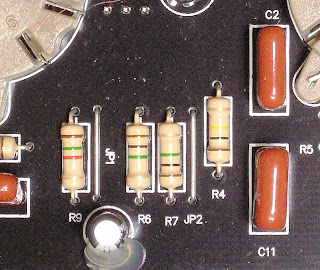


Epiphone Valve Junior R6 R7


These two resistors are in series with the output feeding the next stage being taken at their junction. This a straight ahead voltage divider circuit. R6 and R7 are indicated in red on the schematic below Click on it to see it in full detail.


Epiphone Valve Junior Stock Schematic R6 R7
If you follow the math in the voltage divider posts, you'll see that with two resistors of equal value, as R6 and R7 are here, the voltage at the output will be 50% of the voltage at the input.

That would mean that with 2 Volts output from the first gain stage (V1) the voltage seen by the second stage (V2) would be just 1 Volt.

Things aren't quite that simple in the Valve Junior circuit though. If you look at the schematic you'll see that the 1 Meg volume pot is connected in parallel with R7:


Epiphone Valve Junior Stock Schematic R6 R7 VR1


So the voltage divider is really composed of three resistors - R6 in series with the total resistance of R7 and the volume pot in parallel.

Ok, so that's a bit more complicated. We really want just two resistances to calculate the voltage divider output. Fortunately two resistors in parallel can be treated as a single resistance. We can find the effective resistance of R7 and VR1 in parallel using the following formula:


Formula for the Total Value of Resistors in Parallel


If this formula seems too daunting, the Champion 600 Fat Boost Mod Resistor Values post goes though the details of how to apply it.

Using this formula you'll find that any two resistors of equal value connected in parallel will have a combined value of one half the value of a single resistor.

Incidentally, this is what guides the rule of thumb about connecting speakers in parallel (e.g. two 8 ohm speakers connected in parallel yields a 4 ohm load).

Here we're luck and the two are equal with R7 being 1 Meg and the end to end resistance of the volume pot being 1 Meg. One Megaohm is one million ohms. Half of one million is 500,000 ohms. One thousand ohms is one Kilohm, so the effective resistance of the two in parallel is 500 Kilohms or 500K.

Here is a modified schematic with the parallel resistance of R7 and VR1 shown a a single 500K component:


Epiphone Valve Junior Stock Schematic R6 R7 VR1 Equivalent Circuit
As far as the Valve Junior's functioning is concerned this simplified circuit is the same as the original circuit even though it doesn't indicate the actual physical components. This is what's called an equivalent circuit, and we use it to make the functioning of the circuit easier to comprehend.

So after all of that we have new values for the voltage divider. The top half is still the value of R6 - 1 Meg. The bottom half is now the equivalent resistance of R7 and VR1 in parallel, or 500k.

Using a form of the voltage divider formula we'll find that the output voltage will be about 30% of the input voltage. So with the 2 Volts input given in the example above, our output voltage should be 2 Volts times .3 which equals .6 volts.

You may notice that this .6 Volts is itself the input to another voltage divider - the volume pot itself. You can see how a pot acts a voltage divider in part 3 of the voltage divider post.

So after all that math, it's time for a reality check. Here the right hand meter is connected from the bottom of R7 to the top of R6 - effectively measuring the input voltage to the divider. The left hand meter is connected across R7 - effectively measuring the output voltage feeding the volume pot:


Epiphone Valve Junior Stock Gain Attenuation Measurement
With enough signal applied to achieve 2 Volts from stage 1, the output voltage feeding stage 2 is .6 Volts - right in line with our calculations.

That's a gain reduction in the stock Valve Junior of about 10 dB. That means, of course, that eliminating the voltage divider by jumpering over R6 will result in a 10 dB increase in gain.

So now you know what that 1 Meg R6 is doing in your Valve Junior. Whether or not you want to keep it there is another story entirely.


Friday, January 23, 2009

Fender Champion 600 - Discharging the Filter Caps Pt 2


Here's a more detailed look at discharging the filter caps in a Fender Chapion 600.

First I'll get this out of the way:

THE UBIQUITOUS DISCLAIMER: AKAVALVE ASSUMES NO RESPONSIBILITY FOR THE SAFETY OF ANYONE IMPLEMENTING THESE INSTRUCTIONS. IF YOU ARE NOT FAMILIAR WITH SAFE PRACTICE IN HIGH VOLTAGE CIRCUITS, DO NOT ATTEMPT THIS YOURSELF.


With the amp turned off connect the black lead of the multimeter to ground at the speaker jack. This will be the bare wire connected to the sleeve connection on the jack. You can use any ground connection really, but this on is very easy to get a clip onto. Connect the red lead to the top of R11. Set the meter to read DC Volts. Now flip the amp on.


You'll see the voltage on the meter rise quickly to around 420 volts. If you don't see any voltage reading then you've connected things incorrectly or you meter is not set properly. Don't proceed until you've figured out why you have no reading, and be very careful when when moving the probes as there is now very high voltage in the circuit.

When you have the meter connected properly and are getting a 400+ VDC reading shut off and unplug the amp.


When you shut the amp off you will see the voltage dropping slowly on the meter. You are now ready to connect the clip end of the discharge probe to ground. I find the easiest method is to clip it to the sleeve of the input jack.


Mote that the voltage is still dropping slowly even though the probe hasn't been fully connected. This is because the capacitor is bleeding it's charge though the circuit and through the meter itself. This is exactly what we want the discharge probe to do - but faster.

Now touch the other end of the discharge probe to a source of B+ voltage. Here I'm about to make contact with the red lead of the output transformer primary:


Now you will see the voltage drop quite rapidly. This picture covers the change in just a few seconds (click on it for a close up):


Finally all the voltage will be drained out and you're ready to work on you amp.


Note: Turning the amp on is not really not part of the discharging process. The reason I include it is because it insures that you are getting a good voltage reading and that you can watch that reading drop. That way when your meter shows no voltage you know it's because there is no voltage left in the caps not because the meter isn't connected properly.

Second note: If your speaker is still connected to the amp during this procedure you will notice that the voltage drops fairly quickly. This is because the connected speaker is doing the job of the discharge probe. This is actually a perfectly reasonable way to avoid the discharge probe all together. Discharging with the probe is an excellent habit to get into though because not all amps bleed off their caps voltage so quickly on their own. If you decide to forgo the probe, make sure you are absolutely confident in your voltage measurements in order to stay safe.

Fender Champion 600 - Discharging the Filter Caps Pt 1


Here's the procedure for discharging the filter caps in a Fender Champion 600.


The video is pretty small so I'll put up another post with pictures so the detail is a bit clearer.

I'll cover the construction of the probe in a later post.

THE UBIQUITOUS DISCLAIMER: AKAVALVE ASSUMES NO RESPONSIBILITY FOR THE SAFETY OF ANYONE IMPLEMENTING THESE INSTRUCTIONS. IF YOU ARE NOT FAMILIAR WITH SAFE PRACTICE IN HIGH VOLTAGE CIRCUITS, DO NOT ATTEMPT THIS YOURSELF.


Discharging Filter Caps - The Basics Pt 2


Here's hows how a discharge probe is used to bleed voltage off of a capacitor. This cap is completely removed from the circuit for illustrational purposes, but the procedure is the same when a cap is installed in an amplifier. The meter is tough to read here but I hope it's good enough to get the general idea.


The resistor at the clip end of the probe is a 56K 3 Watt one covered in two layers of shrink tubing for safety. The resistor will limit the current from a 450 Volt supply to under 10 ma but it is still a very good idea not touch the alligator clip end of the probe while connecting the other end to the B+. I'll cover the probe construction in a later post.

THE UBIQUITOUS DISCLAIMER: AKAVALVE ASSUMES NO RESPONSIBILITY FOR THE SAFETY OF ANYONE IMPLEMENTING THESE INSTRUCTIONS. IF YOU ARE NOT FAMILIAR WITH SAFE PRACTICE IN HIGH VOLTAGE CIRCUITS, DO NOT ATTEMPT THIS YOURSELF.


Discharging Filter Caps - The Basics Pt 1


Here are the basic reasons and methods for discharging filter caps. The meter is a little tough to read here but I think it's clear enough to get the basic idea. This is just for illustrational purposes, it's NOT the the method I recommend. I'll cover that in part 2.

THE UBIQUITOUS DISCLAIMER: AKAVALVE ASSUMES NO RESPONSIBILITY FOR THE SAFETY OF ANYONE IMPLEMENTING THESE INSTRUCTIONS. IF YOU ARE NOT FAMILIAR WITH SAFE PRACTICE IN HIGH VOLTAGE CIRCUITS, DO NOT ATTEMPT THIS YOURSELF.


Thursday, January 22, 2009

Fender Champion 600 Free Installation of the Mercury Magnetics Mod


Doing the Champion 600 mods in my previous posts left me with a good bit of curiosity about the specifics of the Mercury Magnetics kit. If anyone in the Boston area has a Champion 600 with a Mercury Magentics mod kit they need to have installed, drop me an email. For the opportunity to get in there and see just what's going on I'd be glad to do the put it free of charge.

Just putting it out there in case anyone's interested...

Friday, January 16, 2009

Fender Champion 600 Fat Boost Mod Resistor Values


In the Fat Switch Mod the circuit sees 3 different resistances for the mid resistor in the tone stack: 15K (stock), 30K (Frondelli Mod fat boost value), and 47K (for a little extra boost). The actual resistors on the switch are quite different values. The 47K value is there but the other two are 68K and 22K. Why not the 15K and 30K that the circuit needs to "see" for the mod?


In order to use a simpler switch I approached the mod a bit differently. I decided to replace the standard mid resistor with a 47K one. This sets the max mid resistor value. The fat switch then selects one of two resistors and connects it in parallel with the 47K resistor, lowering the effective resistance. In the center position both of the additional resistors are disconnected so the total resistance remains 47K.

This should be clear from a schematic drawing:


Too find the effective resistance when one of those resistors is switched in use the formula for finding the total resistance of any number of resistors connected in parallel. Incidentally, this is the same formula you would use when connecting speakers in parallel:


Since we only have two resistors connected at any time, it's a bit simpler. All we need is R1 and R2. Here's how the formula for the 47K resistor in parallel with the switched in 68K resistor is solved in detail:


That 28K value is plenty close to the Frondelli Mod value of 30K. If you're wondering how close, take a look at the graph at the bottom of the Fat Switch Mod post. You'll see from comparing the curves for the three fat boost resistor values that that 2K difference doesn't matter much.

Here's the same equation for the 22K resistor in parallel with the 47K one:


Solve that equation and you'll see that the 22K in parallel with the 47K results in 15K - the same effective value as the original R19. So switching in the 22K resistor puts the tone stack back to stock.

Thursday, January 8, 2009

Fender Champion 600 Cathode Bypass Mod Pt 3


Here's the response curve for the switched cathode bypass caps in part 2 of this post. The first graph is for the stock tone stack:


From top to bottom the curves show:

6V6, 1st stage (12AU7) and 2nd stage (12AX7) engaged (stock).
6V6 and 1st stage (12AU7) engaged.
6V6 bypass cap engaged.
All bypass caps disconnected.


The curves in the next graph follow the same pattern but this time the Tone Stack Bypass is engaged. There is a great deal more gain with the tone stack bypassed. If you click to enlarge the graphs and look at the right hand scale you'll see that the peak response in the modified amp is about 10dB higher than in the stock one.


This amp has the 12DW7 mod installed so the 1st stage has less gain and correspondingly less increase in gain with the cap engaged. In a stock amp the jump from the aqua curve to the green curve would be increased to about the same as the jump between the green curve and the dark purple curve on top.


Tuesday, January 6, 2009

Fender Champion 600 cathode bypass mod Pt 2


When I wrote part 1 of this post I'd been planning to lower the cathode bypass capacitor values in order to clean up the up the bass response. What I ended up doing was removing the cathode bypass capacitors all together in order to get a bit of compression for a fuller low volume clean tone. The effect is a more roundness and a good deal less volume - very nice for a bedroom level clean sound. This meant I needed to find some other ways to control the low end (see the Input Voicing and Presence Plus mods).


For this mod I put in a three pole four position rotary switch that adds the cathode bypass caps in one by one. With the rotary switch the gain of the amp goes up with each setting until it reaches the stock (fully bypassed) position:


This could easily have been three separate switches, but I thought the single control made the operation a bit clearer and didn't clutter up the chassis as much. Since I'm limiting bass response in a couple other ways I ended up keeping the caps at their stock values. The first and second stages could easily have values from part 1 substituted if you have a need for greater bass reduction.

Here is:

THE UBIQUITOUS DISCLAIMER: AKAVALVE ASSUMES NO RESPONSIBILITY FOR THE SAFETY OF ANYONE IMPLEMENTING THESE INSTRUCTIONS. IF YOU ARE NOT FAMILIAR WITH SAFE PRACTICE IN HIGH VOLTAGE CIRCUITS, DO NOT ATTEMPT THIS YOURSELF.

And here's the internal view of the switch with the ground wires in place:


This is how the ground wires hook up:


The wire with the black arrow connects to the lower side of the C4 space on the pc board.

The wire with the blue arrow connects to the lower side of the C10 space on the pc board.

The wire with the red arrow connects to the lower side of the C3 space on the pc board.

Here is the rest of the switch wiring. Notice that the leads for the large blue cap (which serves as C4) jump three pins on the switch.


The stage 2 wire jumper two pins. This wire attaches to the shrinkwrapped end of C10 (indicated by the red arrow).


The wire connecting stage 1 to the switch connects to only one pin. It connects to the shrinkwrapped end of C3 (again, indicated by the red arrow).


If you've removed these caps and are reinstalling them, make sure you observe the proper polarity when you put them back in. The indented end of the cap lines up with the indent in the white outline on the pc board.

For convenience of installation, I replaced the original C4 with a axial lead cap of the same value. It's the large blue cap in the photo below. The negative side of the cap connects to the switch and the positive side is connected to the high side of the pc board connection for C4. The negative lead of the cap holds it pretty well in place but there's a dab of silicone underneath just for good measure.


This switch functions kind of like a staged clean master volume. If you're interested in getting distortion out of your preamp circuit, this mod could be rearranged to serve as a sort of dirty master volume instead. If you're interested let me know and I'll post the details.


Monday, January 5, 2009

Fender Champion 600 Input Voicing Mod Pt 2


Here's a graph showing the frequency response for the Input Voicing Mod. The measurement is taken at the amplifier output with a 4 ohm resistive load.


The top curve is the stock "High" input and the bottom curve is the stock "Low" input. The middle curve shows the response of the "Low" input with the mod installed. Notice that the modded "Low" input is within 1dB of the "High" input for the high frequencies but the lows are rolled off significantly.

I didn't include the modded "High" input response on the graph because it is so close to the unmodded "High" response that it's almost indistinguishable. I would swear I hear a subtle difference between the modded and unmodded "High" input. This may be because the tone generator used for the frequency sweep is non inductive and doesn't react to the input impedance the way a pickup does. Or I may be crazy. If you do this mod yourself, let me know what you hear.

Saturday, January 3, 2009

Fender Champion 600 Tone Stack Bypass/ Fat Switch Mod


This pic shows the shows a few of the mods I've made to this Champion 600. The two small red switches on the bottom of the chassis are for my Presence Plus and Input Voicing modifications. This particular post concerns the tone stack mod associated with the two bigger switches to the upper right.


This mod takes the coupling cap mod from the Tone Stack Test and hardwires it to a switch so the amp can use the stock tonestack or bypass the tonestack with a single coupling cap to eliminate the mid cut in the stock circuit. The right had switch below handles that job. The left switch acts as a three position "fat" switch.

First....

THE UBIQUITOUS DISCLAIMER: AKAVALVE ASSUMES NO RESPONSIBILITY FOR THE SAFETY OF ANYONE IMPLEMENTING THESE INSTRUCTIONS. IF YOU ARE NOT FAMILIAR WITH SAFE PRACTICE IN HIGH VOLTAGE CIRCUITS, DO NOT ATTEMPT THIS YOURSELF.

Here's the finished mod from above:


The combination of resistors on the "fat" switch are selected to combine for three settings:
15K (stock), 30K (Frondelli Mod fat boost value), and 47K (for a little extra boost). The boosts effect the mids most dramatically, but they provide extra gain across the whole spectrum too.

All three resistors connect to the same pin on the right hand switch - the one just to the left of the center pin with the black wire.


The switches I used here each have one more set of contacts than are needed to make the mod. I frequently do this when I'm experimenting so that if I decide to add something to the switch later on I don't need to disassemble the circuit and solder in a new one.

The resistors in the fat boost circuit replace R19 on the pc board. Here's how the wiring runs:


Here's the coupling cap, prepared for installation:


And here it is soldered in place. Since only one end is really fixed and the other will be supporting a wire I put a bead of silicone underneath to make sure it stays in place.


Here's how the wires are run to the switch. Point "A" on the switch runs to point "A" on the board. Same for "B" of course.

Here's the frequency response for the four settings measured at the amp output with a 4 ohm resistive load:


Click on the graph for a high res version. From the bottom to the top the curves are for Stock, Fondelli Mod Fat Boost, Extra Fat Boost and Tone Stack Bypass. The tone stack bypass curve is up about 16dB up at the mid cut frequency!

A final note...if you try this one yourself, be careful to place the switches low enough so they clear the cabinet when you put the chassis back in. It a tight fit.