Showing posts with label Valve Junior. Show all posts

Wednesday, October 21, 2009

Epiphone Valve Junior - the Gain Matrix Mod Part II


I'm going to start describing the Valve Junior Gain Matrix Mod with the physical side of the job. There are three gain stages in the Valve Junior. I'm installing one switch for each of these stages. Here's the chassis marked out for drilling the switch holes:


Valve Junior Gain Reduction Mod - chassis marked for drilling


The switches will change the gain and frequency response by selecting and disconnecting the cathode bypass capacitors. Here is a front of chassis view the three switches installed:


Valve Junior Gain Reduction Mod - switches installed


And here they are from inside the chassis:


Valve Junior Gain Reduction Mod - switches from inside chassis


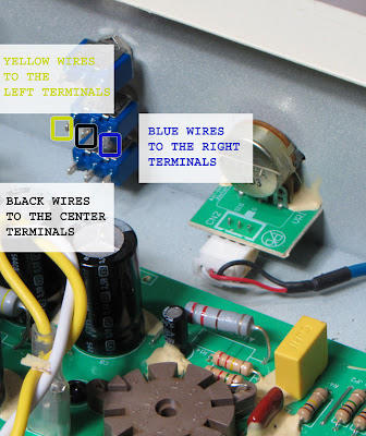
In the following post you'll see that the wires are color coded the wires to make it a bit easier to follow the wiring.
The yellow wires are for the "stock" configuration for each stage.
They connect to the left hand terminal of their respective switch.
The blue wires are for the "mod" value caps.
They connect to the right hand terminals.
The black wires are for ground and they connect to the center terminals:


Valve Junior Gain Reduction Mod - wire color coding


Next up I'll show the actual circuit wiring and in the fourth I'll draw up a schematic for the mod.


Monday, August 3, 2009

Epiphone Valve Junior - the Gain Matrix Mod


Here's a gain reduction mod I recently completed on an Epiphone Valve Junior. The owner was looking for less volume and less gain. This mod has 3 switches each with three positions:


Epiphone Valve Junior gain reduction with the gain matrix mod


With all the switches set to the left the amp is stock. Flipping a switch to the center position reduces the gain by taking the cathode bypass cap for that stage out of the circuit.

Flipping it all the way to the right switches in a different value cap for the cathode bypass. In the right position the upper two switches act as differently voiced bright/body switches and the bottom one acts as a deep switch.

The amp can now be made quiet enough to be used at home. It can be cleaned up for less gainy sounds and brightened for more clarity. And it can be quickly returned to stock if you miss that muddy sound it had when it was new. The various combinations of three switches give a total of 26 alternate voicings.

I shot pictures of this mod but I haven't written up a whole description. If anyone is interested in seeing the whole process, let me know in the comments section of this post and I'll put the details together.


Friday, February 6, 2009

Epiphone Valve Junior - Gain Reduction due to R6 and R7 in a Stock VJ


This post explains a particular part of the Epiphone Valve Junior circuit. If you're looking to reduce the volume and/or gain in your VJ, I started a series of posts for a gain reduction mod.

Here's a schematic for the stock Epiphone Valve Junior:

Epiphone Valve Junior Stock Schematic


There is a voltage divider in the preamp to reduce the overall gain of the amplifier. R6 and R7 are 1 Meg resistors used to form the circuit:
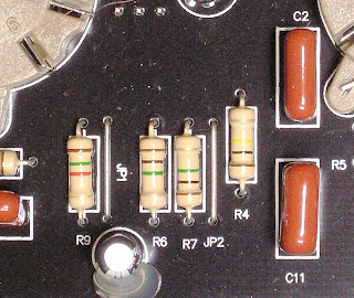


Epiphone Valve Junior R6 R7


These two resistors are in series with the output feeding the next stage being taken at their junction. This a straight ahead voltage divider circuit. R6 and R7 are indicated in red on the schematic below Click on it to see it in full detail.


Epiphone Valve Junior Stock Schematic R6 R7
If you follow the math in the voltage divider posts, you'll see that with two resistors of equal value, as R6 and R7 are here, the voltage at the output will be 50% of the voltage at the input.

That would mean that with 2 Volts output from the first gain stage (V1) the voltage seen by the second stage (V2) would be just 1 Volt.

Things aren't quite that simple in the Valve Junior circuit though. If you look at the schematic you'll see that the 1 Meg volume pot is connected in parallel with R7:


Epiphone Valve Junior Stock Schematic R6 R7 VR1


So the voltage divider is really composed of three resistors - R6 in series with the total resistance of R7 and the volume pot in parallel.

Ok, so that's a bit more complicated. We really want just two resistances to calculate the voltage divider output. Fortunately two resistors in parallel can be treated as a single resistance. We can find the effective resistance of R7 and VR1 in parallel using the following formula:


Formula for the Total Value of Resistors in Parallel


If this formula seems too daunting, the Champion 600 Fat Boost Mod Resistor Values post goes though the details of how to apply it.

Using this formula you'll find that any two resistors of equal value connected in parallel will have a combined value of one half the value of a single resistor.

Incidentally, this is what guides the rule of thumb about connecting speakers in parallel (e.g. two 8 ohm speakers connected in parallel yields a 4 ohm load).

Here we're luck and the two are equal with R7 being 1 Meg and the end to end resistance of the volume pot being 1 Meg. One Megaohm is one million ohms. Half of one million is 500,000 ohms. One thousand ohms is one Kilohm, so the effective resistance of the two in parallel is 500 Kilohms or 500K.

Here is a modified schematic with the parallel resistance of R7 and VR1 shown a a single 500K component:


Epiphone Valve Junior Stock Schematic R6 R7 VR1 Equivalent Circuit
As far as the Valve Junior's functioning is concerned this simplified circuit is the same as the original circuit even though it doesn't indicate the actual physical components. This is what's called an equivalent circuit, and we use it to make the functioning of the circuit easier to comprehend.

So after all of that we have new values for the voltage divider. The top half is still the value of R6 - 1 Meg. The bottom half is now the equivalent resistance of R7 and VR1 in parallel, or 500k.

Using a form of the voltage divider formula we'll find that the output voltage will be about 30% of the input voltage. So with the 2 Volts input given in the example above, our output voltage should be 2 Volts times .3 which equals .6 volts.

You may notice that this .6 Volts is itself the input to another voltage divider - the volume pot itself. You can see how a pot acts a voltage divider in part 3 of the voltage divider post.

So after all that math, it's time for a reality check. Here the right hand meter is connected from the bottom of R7 to the top of R6 - effectively measuring the input voltage to the divider. The left hand meter is connected across R7 - effectively measuring the output voltage feeding the volume pot:


Epiphone Valve Junior Stock Gain Attenuation Measurement
With enough signal applied to achieve 2 Volts from stage 1, the output voltage feeding stage 2 is .6 Volts - right in line with our calculations.

That's a gain reduction in the stock Valve Junior of about 10 dB. That means, of course, that eliminating the voltage divider by jumpering over R6 will result in a 10 dB increase in gain.

So now you know what that 1 Meg R6 is doing in your Valve Junior. Whether or not you want to keep it there is another story entirely.


Saturday, January 31, 2009

What is a voltage divider? Pt3


Part 1
of this post showed a voltage divider made with two resistors connected end to end:


It's a useful circuit, but it's action is fixed - determined be the value of the resistors chosen for the circuit. A potentiometer (commonly called a "pot") is a variable resistor and it can easily be wired to form a variable voltage divider.

A pot generally has three pins. The outer two pins connect to the opposites ends of the pot's resistive track. The resistance from one end of a pot to the other never changes. In this example it's 500 ohms.


The pot's center pin is connected to the wiper. The wiper moves along the resistive track as the pot is turned. Because the wiper simply splits total resistance into two parts, the sum of those two resistances is always equal to the total resistance from end to end. In this case 250 ohms + 250 ohms = 500 ohms.

To the circuit this looks like two 250 ohm resistors connected in series. Putting volts across the ends of the pot as we did in part 1 causes 1.5 volts to appear from each end of the pot to the wiper.


So what happens when the pot is turned?

The resistance from end to end stays the same but the way that resistance is divided by the wiper changes:


Here the position of the wiper makes the pot function like a 100 ohm and a 400 ohm resistor connected in series. Following the rules from part 1 again, 3 volts in will produce 2.4 volts out.


If the pot is turned toward the other end of it's rotation and the resistances are reversed:


Now 3 volts at the input yields only 0.6 volts at the output:


This is just what is happening when you turn down the volume knob on your guitar or amplifier.

The Epiphone Valve Junior has both a fixed voltage divider for reducing the gain between stages and a variable voltage divider (the volume pot) wired in parallel. In the next post I'll take a look at that circuit as a real world example.

Saturday, December 13, 2008

Fender Champion 600 vs Epiphone Valve Junior


Here's a frequency plot of a stock Epiphone Valve JR and a stock Champion 600, each using the Eminence Legend 12" speaker in a Fender Deluxe Cab.

Notice the relative low frequency roll off and the 725 HZ bump on the Valve Junior plot.

What's not evident here is that the gain setting on the Champion 600 is at about 12:00 the gain on the Valve Junior is about 9:00 for the same output.