Showing posts with label Resistors. Show all posts

Monday, April 27, 2009

Are these two resistors different?


One of the first steps you'll read in any set of tube amp troubleshooting instructions is "visual inspection". It just means looking over the components for any obvious signs of stress. Here I've stuck two 100K resistors in a piece of foam for the sake of comparison.


Fender '65 Twin Reissue failed plate resitor


Looking at the two 100K resistors pictured an astute observer might notice the slightly darker midsection of the upper resistor. It's fairly subtle here and even more so when it's still in the circuit, not positioned right next to a normal looking one.


These resistors are plate resistors taken from a Fender '65 Twin Reissue that came in with a broken Normal channel. The resistor that shows slight signs of overheating was completely open. It was passing no current at all, effectively shutting off the tube. It might as well have not have even been in the circuit. I replaced it to get the channel working again.


So why did I take out both resistors? Well the second one is actually completely open as well, it just doesn't happen to show any visible signs of fatigue.


That's the trick with visual inspection. It's a very good first step. But troubleshooting effectively means knowing how to use your meter to see for you. Parts can fail in many ways that you never have any hope of catching with your eyes.


Monday, March 2, 2009

Fender Champion 600 Preamp Bias Part 2b


In Preamp Bias Part 2a we derived this load line for the first 12AX7 gain stage:


12AX7 preamp biasing - the load line

To find the maximum current we imagined that the full preamp B+ voltage was across the plate resistor. This post is an addendum to for those interested in why that is a reasonable way to estimate the maximum current. First we should look as the path of the current from the B+ power supply to ground:


12AX7 preamp biasing - current flow

From the 340VDC power supply the current flows through the plate resistor, on through the tube itself and then through the cathode resistor to ground.* So here's what he circuit "looks like" for DC current flow:


12AX7 preamp biasing - simplified current flow

So there are three separate resistances to the flow of current. All three are in series so the total resistance will be all three of those resistance added together. Using Ohm's law again:


ohms law


The total current flowing in the circuit will be 340 volts divided by the the total of those three resistances.

From both Ohm's law and from intuition we know that more resistance will mean more opposition to current flow. Hence less resistance will mean more current flow.

So to find the maximum current flow we want to be thinking of the condition under which the circuit has the least possible resistance.


This means that we have to make all three of those resistances as small as possible. The plate resistor (Rp) is a fixed value of 100,000 ohms - nothing we can do about that.

The cathode has a fixed resistor too (Rk) - 1500 ohms. It's value is not going to change either.

The internal plate resistance (ra) is the resistance the tube itself contributes to the circuit. This value varies very widely - practically from zero to infinity. This change in resistance is actually key to it's functioning as an amplifier.

We want to be calculating the point at which the total resistance is smallest. Since that will occur when the tube's internal resistance is smallest we'll use the smallest possible internal resistance in our calculation. That makes things easy. That's effectively zero.

So that leaves us with the following:


12AX7 preamp biasing - total resistance

That means the total resistance is just the sum of the plate resistor value and the cathode resistor value.

But in Part A I said all we used to calculating the maximum current is the plate resistor value. Now we're using the cathode resistor too. Why the change?

There's no change really. The cathode resistor is very small compared to the plate resistor - only 1.5% of the value so we can ignore it for the calculation. If you're designing a stage from scratch you won't pick the cathode value until after you've drawn the load line so it's easiest to be in the habit of ignoring it for the common stages you'll find in most guitar amps.


* Capacitors block DC. Since we're looking at the DC current flow, no current will be flowing through any of the capacitors.

Fender Champion 600 Preamp Bias Part 2a


The the last post we found one of two points we need to draw the load line for first 12AX7 gain stage in a Champion 600. We'll use the load line to find the bias point and later reset that bias point for the 12DW7 mod.

The first point was found by simply plotting the B+ voltage on the X axis of the 12AX7 plate curves:


Fender Champion 600 12AX7 Plate Curves with Maximum Plate Voltage indicated


Now we need to find the maximum plate current. To do this we use Ohm's Law to calculate how much current will flow with the full B+ voltage dropped across the plate resistor.


We know the B+ is 340 volts and the plate resistor is 100,000 ohms.

340 divided by 100,000 is .0034 amps or 3.4 milliamps

Now we plot 3.4 mA onto the Y axis and connect that dot to the one we made on the X axis:


The line connecting these two points is what's called a "load line" and it's what we use to determine the bias point for the tube. I'll cover the bias point in an upcoming post.


Thursday, February 26, 2009

Fedner Champion 600 12DW7 / ECC832 Mod Part 1 - Update


I'm focusing here on the 12DW7 / ECC832 partly out of curiosity and partly because it's half the work to rebias for the new tube. What is a 12DW7? Technical details can be found in the 12DW7 mod part 2.

The goal of the mod is to get a good bedroom level clean sound with a more useful range in the volume control. You can lower the gain and get more headroom by substituting a 12AT7,12AY7 or 12AU7 for the 12AX7. It won't be biased properly, but you may like the sound anyway and you're not going to hurt anything.

You can also plug a 12DW7/ECC832 in place of a 12AX7. A 12DW7 / ECC832 is one half 12AX7 and one half 12AU7. If you like the sound, try this mod to bias the lower mu half of the tube correctly.

THE UBIQUITOUS DISCLAIMER: AKAVALVE ASSUMES NO RESPONSIBILITY FOR THE SAFETY OF ANYONE IMPLEMENTING THESE INSTRUCTIONS. IF YOU ARE NOT FAMILIAR WITH SAFE PRACTICE IN HIGH VOLTAGE CIRCUITS, DO NOT ATTEMPT THIS YOURSELF.

All it takes is a 12K resistor jumpered in parallel with the stock 100K plate resistor R8 and a 1K resistor in parallel with the 1.5K cathode resistor R2. They're the two dark brown 3 watt IRC resistors shown in the middle of the picture.


The effect of putting 2 resistors in parallel is to reduce the overall resistance:


So the stock plate resistor in parallel with the additional 12K one gives a combined value of 10.7K for the plate. This greatly increases the current through the tube, which is what we need for a 12AU7.

With the current increased we need to change the bias of the stage to suit a 12AU7. With the stock resistor it will be running quite cold. The added 1K resistor in parallel with the stock 1.5K one yields a total resistance of 600 ohms.

If you're interested, the working through of the parallel resistance formula is covered in more depth in the Fat Boost Resistor Value post.


Here's a close up of the plate resistor. This jumpering method makes it very easy to remove the mod if you decide to go back to stock.


You can see below that the joint on the left hand of the plate resistor is not perfect - the solder hasn't flowed onto the lead of the original as completely as one would like. This is just for a listening test though so I didn't bother touching it up.


With this mod in place the amp is much cleaner and much quieter. It's important to note that you should NOT plug a 12AX7 back into the socket with the mod in place. A 12AX7 triode can't handle the amount of current that a 12AU7 triode can, so half of your 12AX7 will be toasted by the rebiased stage.


Friday, February 6, 2009

Epiphone Valve Junior - Gain Reduction due to R6 and R7 in a Stock VJ


This post explains a particular part of the Epiphone Valve Junior circuit. If you're looking to reduce the volume and/or gain in your VJ, I started a series of posts for a gain reduction mod.

Here's a schematic for the stock Epiphone Valve Junior:

Epiphone Valve Junior Stock Schematic


There is a voltage divider in the preamp to reduce the overall gain of the amplifier. R6 and R7 are 1 Meg resistors used to form the circuit:
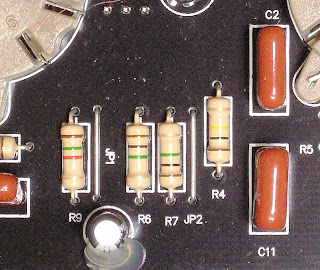


Epiphone Valve Junior R6 R7


These two resistors are in series with the output feeding the next stage being taken at their junction. This a straight ahead voltage divider circuit. R6 and R7 are indicated in red on the schematic below Click on it to see it in full detail.


Epiphone Valve Junior Stock Schematic R6 R7
If you follow the math in the voltage divider posts, you'll see that with two resistors of equal value, as R6 and R7 are here, the voltage at the output will be 50% of the voltage at the input.

That would mean that with 2 Volts output from the first gain stage (V1) the voltage seen by the second stage (V2) would be just 1 Volt.

Things aren't quite that simple in the Valve Junior circuit though. If you look at the schematic you'll see that the 1 Meg volume pot is connected in parallel with R7:


Epiphone Valve Junior Stock Schematic R6 R7 VR1


So the voltage divider is really composed of three resistors - R6 in series with the total resistance of R7 and the volume pot in parallel.

Ok, so that's a bit more complicated. We really want just two resistances to calculate the voltage divider output. Fortunately two resistors in parallel can be treated as a single resistance. We can find the effective resistance of R7 and VR1 in parallel using the following formula:


Formula for the Total Value of Resistors in Parallel


If this formula seems too daunting, the Champion 600 Fat Boost Mod Resistor Values post goes though the details of how to apply it.

Using this formula you'll find that any two resistors of equal value connected in parallel will have a combined value of one half the value of a single resistor.

Incidentally, this is what guides the rule of thumb about connecting speakers in parallel (e.g. two 8 ohm speakers connected in parallel yields a 4 ohm load).

Here we're luck and the two are equal with R7 being 1 Meg and the end to end resistance of the volume pot being 1 Meg. One Megaohm is one million ohms. Half of one million is 500,000 ohms. One thousand ohms is one Kilohm, so the effective resistance of the two in parallel is 500 Kilohms or 500K.

Here is a modified schematic with the parallel resistance of R7 and VR1 shown a a single 500K component:


Epiphone Valve Junior Stock Schematic R6 R7 VR1 Equivalent Circuit
As far as the Valve Junior's functioning is concerned this simplified circuit is the same as the original circuit even though it doesn't indicate the actual physical components. This is what's called an equivalent circuit, and we use it to make the functioning of the circuit easier to comprehend.

So after all of that we have new values for the voltage divider. The top half is still the value of R6 - 1 Meg. The bottom half is now the equivalent resistance of R7 and VR1 in parallel, or 500k.

Using a form of the voltage divider formula we'll find that the output voltage will be about 30% of the input voltage. So with the 2 Volts input given in the example above, our output voltage should be 2 Volts times .3 which equals .6 volts.

You may notice that this .6 Volts is itself the input to another voltage divider - the volume pot itself. You can see how a pot acts a voltage divider in part 3 of the voltage divider post.

So after all that math, it's time for a reality check. Here the right hand meter is connected from the bottom of R7 to the top of R6 - effectively measuring the input voltage to the divider. The left hand meter is connected across R7 - effectively measuring the output voltage feeding the volume pot:


Epiphone Valve Junior Stock Gain Attenuation Measurement
With enough signal applied to achieve 2 Volts from stage 1, the output voltage feeding stage 2 is .6 Volts - right in line with our calculations.

That's a gain reduction in the stock Valve Junior of about 10 dB. That means, of course, that eliminating the voltage divider by jumpering over R6 will result in a 10 dB increase in gain.

So now you know what that 1 Meg R6 is doing in your Valve Junior. Whether or not you want to keep it there is another story entirely.


Friday, January 30, 2009

What is a voltage divider? Pt 2


To help visualize the concept from part 1 of this post, here's a quick circuit mock up of the circuit diagrammed there. On the left is a 10 ohm resistor with the left hand meter's probes connected across it. Connected in series to this resistor is a 90 ohm one with the right hand meters leads connected across it.


Below the meters are reading the actual values of their respective resistors (10.4 ohms to the left and 91.4 ohms to the right). This works out to pretty much the 10% and 90% of total resistance as shown in part 1.


Now the power supply is connected to the circuit and turned on.


The left hand resistor is seeing o.233 volts and the right hand one is seeing 2.112 volts. The sum of the voltage drops across the two resistors is 2.345 volts.

o.233 divided by 2.345 is .101 or about 10%
2.112
divided by 2.345 is .901 or about 90%


The voltage is raised to about 4.5 volts on the power supply.

Now the left hand resistor is seeing 0.439 volts and the right hand one is seeing 3.99 volts. The sum of those voltage drops 4.429 volts.

0.439 divided by 4.429 is .099 or about 10%
3.99
divided by 4.429 is .903 or about 90%


The voltage is raised again to about 10 volts on the power supply.

Now the left hand resistor is seeing 1.010 volts and the right hand one is seeing 9.05 volts. The sum of those voltage drops 10.06 volts.

1.01 divided by 10.06 is .1 or about 10%
9.05
divided by 10.06 is .899 or about 90%

So no matter how the voltage changes the ratio between the voltages across the resistors stays the same.

With an output connected across the 90 ohm resistor (as shown in part 1), any voltage input to the circuit will produce 90% of that voltage at the output. Now you can see how the voltage divider is effective for the constantly changing AC signal generated by your guitar as well as for a simple DC circuit.


What is a voltage divider? Pt1


You'll find voltage dividers in a whole host of places throughout your amp, your pedals and even in your guitar itself.

So what is it? And what does it do?


There are other applications, but one common use is as attenuators to reduce the voltage between stages. Once you understand the basic concept it's use in more complicated instances (like the divider formed with your plate load resistors) will be much easier to grasp.

The simplest sort is formed with two resistors hooked up in series:


You'll see that the total resistance from the top of the first resistor (R1) to the bottom of the second (R2) is just the sum of the two resistors (Rtotal).

Rtotal makes up 100% of the total resistance of the circuit. The 10 ohm resistor R1 makes up one tenth of the total resistance - so .1 or 10%. R2 makes up the remainder, or 90%.


So let's put a voltage across the two resistors, say 3 Volts:


The full voltage, 3 volts, could be measured across the two resistors. If you add the voltages that appear across each of the resistors individually they must equal the total voltage of 3 volts. How much voltage appears across each resistor?

Take resistor R1. It makes up 10% of the total resistance of the circuit. Take 10% of the total voltage (that's 3 times .1) and you'll get the voltage drop across R1. That's .3 volts.

Do the same for R2 (3 times .9) and you'll get 2.7 volts.

Add those two and you'll get 3 volts. So things check out.

Now because we're looking at voltage not current we can change the resistances and get the same results as long as the ratio between R1 and R2 stays the same.

Here's the same circuit with R1=50 ohms and R2=450 ohms:


When you do the math:

R1 divided by Rtotal = 500/50 = .1 or 10%
R2 divided by Rtotal =500/450 = .9 or 90%


You can see this is the same as in the previous example.

So why does all this matter? Let's imagine the resistors in a more complete circuit:


Here imagine that the input is coming from one amplifier stage the output is feeding the next stage. If we look again at how the voltages divide across the resistors:


You'll see that with 3 volts of input you a .3 volt drop and the output voltage is reduced to 2.7 volts. Changing the values of the resistors can change the amount of drop. If you use a variable resistor (a potentiometer or "pot") you can vary the drop by turning the knob on the pot. This is exactly how the volume knobs on you guitar and amplifier work. I'll cover that in more detail in part 3.


Friday, January 23, 2009

Fender Champion 600 - Discharging the Filter Caps Pt 1


Here's the procedure for discharging the filter caps in a Fender Champion 600.


The video is pretty small so I'll put up another post with pictures so the detail is a bit clearer.

I'll cover the construction of the probe in a later post.

THE UBIQUITOUS DISCLAIMER: AKAVALVE ASSUMES NO RESPONSIBILITY FOR THE SAFETY OF ANYONE IMPLEMENTING THESE INSTRUCTIONS. IF YOU ARE NOT FAMILIAR WITH SAFE PRACTICE IN HIGH VOLTAGE CIRCUITS, DO NOT ATTEMPT THIS YOURSELF.


Discharging Filter Caps - The Basics Pt 2


Here's hows how a discharge probe is used to bleed voltage off of a capacitor. This cap is completely removed from the circuit for illustrational purposes, but the procedure is the same when a cap is installed in an amplifier. The meter is tough to read here but I hope it's good enough to get the general idea.


The resistor at the clip end of the probe is a 56K 3 Watt one covered in two layers of shrink tubing for safety. The resistor will limit the current from a 450 Volt supply to under 10 ma but it is still a very good idea not touch the alligator clip end of the probe while connecting the other end to the B+. I'll cover the probe construction in a later post.

THE UBIQUITOUS DISCLAIMER: AKAVALVE ASSUMES NO RESPONSIBILITY FOR THE SAFETY OF ANYONE IMPLEMENTING THESE INSTRUCTIONS. IF YOU ARE NOT FAMILIAR WITH SAFE PRACTICE IN HIGH VOLTAGE CIRCUITS, DO NOT ATTEMPT THIS YOURSELF.


Friday, January 16, 2009

Fender Champion 600 Fat Boost Mod Resistor Values


In the Fat Switch Mod the circuit sees 3 different resistances for the mid resistor in the tone stack: 15K (stock), 30K (Frondelli Mod fat boost value), and 47K (for a little extra boost). The actual resistors on the switch are quite different values. The 47K value is there but the other two are 68K and 22K. Why not the 15K and 30K that the circuit needs to "see" for the mod?


In order to use a simpler switch I approached the mod a bit differently. I decided to replace the standard mid resistor with a 47K one. This sets the max mid resistor value. The fat switch then selects one of two resistors and connects it in parallel with the 47K resistor, lowering the effective resistance. In the center position both of the additional resistors are disconnected so the total resistance remains 47K.

This should be clear from a schematic drawing:


Too find the effective resistance when one of those resistors is switched in use the formula for finding the total resistance of any number of resistors connected in parallel. Incidentally, this is the same formula you would use when connecting speakers in parallel:


Since we only have two resistors connected at any time, it's a bit simpler. All we need is R1 and R2. Here's how the formula for the 47K resistor in parallel with the switched in 68K resistor is solved in detail:


That 28K value is plenty close to the Frondelli Mod value of 30K. If you're wondering how close, take a look at the graph at the bottom of the Fat Switch Mod post. You'll see from comparing the curves for the three fat boost resistor values that that 2K difference doesn't matter much.

Here's the same equation for the 22K resistor in parallel with the 47K one:


Solve that equation and you'll see that the 22K in parallel with the 47K results in 15K - the same effective value as the original R19. So switching in the 22K resistor puts the tone stack back to stock.

Tuesday, December 23, 2008

Float Your Screen Resistors!


Here's a pretty extreme example of what happens when you
screen resistors are too close to the pc board. This is why it's important
to "float" higher power resistors off the circuit board.


The amp here is an Ampeg V4B. The board was so burned that the
screen resistors were moved off to the power tube sockets.
The resistors that burned up were replacements,
the originals would have been underneath the pc board.

In the center of the picture below is a floated resistor in a
Fender Champion 600. The breathing room beneath
the resistor reduces the chance of the pc board being
damaged if the resistor overheats or flames out.


It's shocking that some new production amps don't bother
to do this as their pc boards are generally very delicate.
There is no really effective way to repair a pc board
once it goes. Your tech can kludge in jumper wires
but the amp will never be "like new".


Tuesday, December 16, 2008

Inside the Fender Champion 600


There are a few relatively pleasant surprises inside the Champion 600.
Granted, the bar is pretty low for current production budget amps,
but here's a few things I was glad to see.


Fender Champion 600 mod power resistor

The 3 higher power resistors are all floated well off the circuit board
(one of them is shown in the middle above).
This allows them to dissipate heat more effectively and keeps them
from cooking the pc board when they get hot.


Modding the Fender Champion 600 - 6V6 octal socket
Even though the octal socket for the 6V6 is mounted to the pc board, the socket also screws to the chassis when the amp is fully assembled. When it's screwed down it has a pretty decent mechanical connection. Not perfect, but better than average for today's amps.

There are plenty of amps in which the only mechanical support for the tube socket is the solder that makes the electrical connections for the tube pins. These inevitably get strained when tubes are taken in out. Usually they cause an annoying intermittent failure long before they crap out completely.


Modding the Fender Champion 600 - 12AX7 preamp socket

The 9 pin preamp tube socket isn't quite as good but better than a lot I've seen. It's mounted directly to the board with no independent mechanical support. The top ring on the socket fits pretty snugly into the hole in the chassis. The pc board mounting screws are close enough to the socket that the board doesn't flex too much when the tube is wiggled out of place.


Modding the Fender Champion 600 - input jacks volume pot

The plastic jacks are better than I expected them to be. And the way the small front panel circuit board is implemented it would be easy to eliminate the card completely and replace the jacks and the volume pot with more robust components. There's also plenty of real estate immediately available for switches and such - both under the chassis and on the front panel. I'm planning to have a few switches in there, at least for the testing phase, so it's nice to have the space.


Friday, December 5, 2008

carbon comp v.s. metal film resisitors


This is another test post of sorts - seeing how well the video works.

The videos show a comparison of the heat stability of metal film resistors compared to the traditional carbon comp ones.

After watching the video, imagine what those carbon comp screen resistors hanging over the top of the tube socket of your old Fender are doing as your amp heats up. They aren't going to get as hot as they do when hit with the heat gun. But if you imagine all the carbon comps in your amp drifting a bit with heat you can imagine the amp's not going to sound the same. Might be better might be worse but it won't be consistent.

Here's the IRC metal film one:


And the carbon comp: