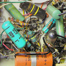
I'm building up a low wattage tube practice amp roughly
based on an old Gregory Gemini 700 / Mark 5.
Since the circuit is pretty simple, the process may help you to learn
how to translate a schematic diagram into an actual tube amp layout.
Here's a schematic for the No. 2 version of the Gregory:
based on an old Gregory Gemini 700 / Mark 5.
Since the circuit is pretty simple, the process may help you to learn
how to translate a schematic diagram into an actual tube amp layout.
Here's a schematic for the No. 2 version of the Gregory:

So how do I get from that schematic to this:

It's not too difficult if you take it one step at a time.
I'll show you loosely how I approached it for this one.
First have a look at the schematic and try to divide it into functional blocks.
That will keep you from getting confused as you go along.
It'll also be much easier to troubleshoot if everything doesn't work on the first try.
Below I've boxed the preamp stage in red, the tremolo section in orange,
and the power and output section in black:

Now you need to figure out what the components are actually
going to be physically and electrically attached to.
I find that some kind of tagboard or turret board makes the planning
and subsequent wiring neat and easy to follow.
I picked this board from Antique Electronic Supply.
going to be physically and electrically attached to.
I find that some kind of tagboard or turret board makes the planning
and subsequent wiring neat and easy to follow.
I picked this board from Antique Electronic Supply.

Now on a sheet of graph paper I drew in the components
for the individual amp stages in colors that match
the sections I indicated on the schematic.
Then I drew in all the connections that would need
to be made according to the schematic.
At this point check and double check you work.
This drawing is done imagining the tagboard oriented vertically.
Each of the rectangles relates to one resistor or capacitor in the circuit
and the lines represent connections between them.
I do this stuff pretty regularly, so you'll see I'm not super fussy about neatness or corrections.
You'd want to be a bit more careful yourself until you can rely on your instincts to catch errors:

There also components which will not be mounted on your board
(control pots, tube sockets, transformers etc).
I've been lazy here and only indicated the pots.
They're in green on my hand drawing and circled in green on the schematic below.
You should probably be careful to include them all if you haven't done this before.
Thoroughness will pay off in the end.
(control pots, tube sockets, transformers etc).
I've been lazy here and only indicated the pots.
They're in green on my hand drawing and circled in green on the schematic below.
You should probably be careful to include them all if you haven't done this before.
Thoroughness will pay off in the end.

Now turn the layout drawing in the same direction as the tag board
and you're ready to start soldering:
and you're ready to start soldering:

I install all the components first and then move onto the connections.
Here are the caps and resistors installed on the board:

And here's the board with the electrical connection in place:

Now all that's left is to install the board and make the connections
to the chassis mounted components and fire it up to see if it works!
If you're paying very close attention, you'll notice that my layout
drawing doesn't match the schematic drawing exactly
(and the board doesn't exactly match the drawing).
I've made some changes as I been working on these amps
but I haven't drawn up a revised schematic yet.
The one here should serve well enough for the example though.


