Thursday, March 19, 2009

Fender Champion 600 hum reduction mod


The Champion 600 I've been working on came back in with a request for the cathode referenced heater mod to reduce the hum. For a single ended amp this particular one is actually pretty quiet already. It certainly hums less than any of the vintage Champs I've seen. I don't mind a little bit of hum myself but the owner is new to tube amps so he's a bit more sensitive to it than I am. The mod is a real simple one though so I thought I'd take a crack at it and see if it did anything.


R15 and R16 are the resistors that reference the heater filaments to ground. A old trick for single ended amps is to move the end of these resistors to the cathode of the output tube.

Since I've moved the cathode bypass cap as part of another mod, I had a convenient place to connect the resistors. If the cap is still there the resistors could be connected to the top of R10 instead (indicated by the red circle).


Here's a measurement taken off the output with a 4 ohm dummy load connected:


You'll notice that there's almost no reduction in the fundamental or even any of the lower harmonics. It's not until about 2K Hz that we start to see a reduction in the hum. As I mentioned earlier, this amp was pretty quiet to begin with. Curiously the owner actually perceived it as humming slightly more with the mod installed so I'm going to put it back to stock when it comes back in to get a Weber Alnico speaker put in.

Sunday, March 8, 2009

Fender Champion 600 Preamp Bias Part 5


Now I'm finally going to get down to talking about biasing. Instead of giving a wordy definition of bias I'm going to try to focus on some details of the circuit that will give you an intuitive sense of what bias is and why we need it. Once you have a grasp of those the textbook definitions should begin to make more sense.


Part 4 of the preamp bias posts showed where to connect your meter leads to measure the B+ voltage, plate voltage and grid voltage in the first 12AX7 gain stage in a Champion 600. Those measurements will all come into play later on. Right now we're going connect the meter in another way to read the cathode voltage.


measureing the voltage drop on the cathode resistor


Zooming in on the schematic, we see this label (which I've highlighted in blue):


Fender Champion 600 TP6


It says +1.7 VDC / TP6. This means we should see a reading of positive 1.7 volts of DC at Test Point Six. The line extending from the label box indicates where the meter would be connected to take this reading.

All of the test point measurements (and in fact the majority of the measurements you'll take inside any amp) are "referenced to ground". What that means practically is that the point you connect the black lead of you meter should have no components between it and ground.

This is the symbol for ground on a schematic:


schematic symbol for ground


So looking back at the schematic above you'll see that the way our meter is connected is measuring the cathode voltage "referenced to ground".

Now back to our cathode resistor. Since a capacitor blocks DC current and it's a DC measurement we're concerned with we'll ignore the cap for the moment:


Fender Champion 600 Test Point 6


That leaves us with 1.7 volts measure across a 1.5K resistor. That means we have enough information to calculate the current through the resistor using Ohm's law.

ohms law


1.7 volts divided by 1,500 ohms is .0011 amps - or 1.1 ma.

It's no mistake that this 1.7 volts at the grid and 1.1 ma of current fall right at point C on the graph of plate curves we've been looking at:


Champion 600 12AX7 preamp bias point


The circuit designer chose point C to be the bias point. Given the load line they had to choose the 1.5K resistor to make that happen. The next post will explain why.


Friday, March 6, 2009

Fender Champion 600 Preamp Bias Part 4


In the last post we left off with three points whose combination of current and voltage fell along the load line:


12AX7 load line for a stock Fender Champion 600


This whole load line business gets a bit abstract and that can make it hard to think about it in terms of the actual circuit. To try to bring it back to earth a bit (or at least back to the schematic) here's a picture illustrating where that plate voltage appears in the circuit*:


connecting a meter to read preamp plate voltage on a champion 600


If you were to connect your meter's red and black leads to the points indicated in the schematic the voltage you'd be reading on the meter would be the voltage that appears on the X axis of the plate curves graph we've been working with. We'll see later that this voltages changes a great deal depending on the bias point and the nature of the signal that is connected to the input. The fact that this voltage changes according to the input is exactly what makes the tube function as an amplifier.

Move the red lead to the other side of the plate resistor and you'd be reading the B+ voltage. This voltage should remain pretty much constant with signal applied or without:


connecting a meter to read preamp B+ voltage on a champion 600


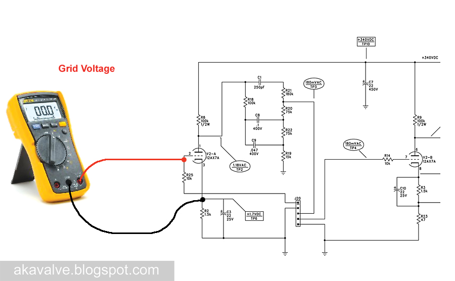
Now move both leads and you'll be reading the grid voltage:


connecting a meter to read grid voltage on a champion 600


The grid voltage is indicated on the plate curves as well. Here is the graph with the load line again. Have a look at the top end of the curves - you'll see a voltage label on each of them:


grid voltage for a 12AX7By following the grid voltage curve to it's intersection with the load line, you can see what grid voltage (-0.5 volts) that corresponds to the plate voltage and current we've chosen at point A:


Grid voltage plotted on the load line for a 12AX7 gain stage in a Champion 600


Since the grid voltage curves are pretty widely space you have to guesstimate when the points on the load line fall in between curves. I've done that here for points B and C.


Grid voltage plotted for three points on the load line for a 12AX7 gain stage in a Champion 600


Using these points and the three values associated with each of them we can calculate the value of the cathode resistor in order to set the bias. We can also use them to calculate the gain of the stage. We'll do that in the next post.


* This is the plate voltage relative to ground. There are times when you need to measure the plate voltage relative to the cathode but this measurement will work fine for what we're concerned with here.


Wednesday, March 4, 2009

Fender Champion 600 Preamp Bias Part 3


In Part 2a we plotted the maximum current for the first 12AX7 gain stage in a Champion 600. That point was connected to the maximum voltage point to find what's called the load line for the stage.


This is the place to come to terms with a essential concept. Every point on the graph of plate curves represents a possible combination of plate voltage and plate current for a 12AX7. Let's choose a few for the sake of illustration. Let's pick Point A at 1.1 milliamps of plate current and 140 volts at the plate. Here's that point graphed onto the 12AX7 plate curves:


Now we'll pick another one we'll call Point B at 0.4 millamps of plate current and 230 volts at the plate. Here's that point graphed onto the 12AX7 plate curves:


Now we'll a third, Point C, at 1.1 milliamps of plate current and 230 volts at the plate. Here's that point graphed onto the 12AX7 plate curves:

Here's the fundamental concept. The load line we've drawn crosses all the possible combinations of voltage and current that can occur in our circuit given the 100K plate load we've chosen - so any dot which plots a combination of current and voltage must lie on this line for it to be a possible occurance in the circuit. We've plotted three different points but only Point C lies on the load line. When the circuit is drawing 1.1 mA of plate current the plate voltage must be the 230 volts indicated by point C NOT the 140 volts indicated by Point A. And with 230 Volts on the plate the circuit must draw 1.1 mA as indicated by Point C, NOT the .4 mA indicated by Point B.

The load line indicates that Point A and Point B do not exist for the circuit given our chosen 100K plate load. Points A and B can still exist as long as we adjust either the current or the voltage so that they lie on the load line:

This all may seen somewhat abstract, but it's essential to understanding the biasing of the preamp stage. It should all become clearer as we begin to discuss bias in the next few posts.

Monday, March 2, 2009

Fender Champion 600 Preamp Bias Part 2b


In Preamp Bias Part 2a we derived this load line for the first 12AX7 gain stage:


12AX7 preamp biasing - the load line

To find the maximum current we imagined that the full preamp B+ voltage was across the plate resistor. This post is an addendum to for those interested in why that is a reasonable way to estimate the maximum current. First we should look as the path of the current from the B+ power supply to ground:


12AX7 preamp biasing - current flow

From the 340VDC power supply the current flows through the plate resistor, on through the tube itself and then through the cathode resistor to ground.* So here's what he circuit "looks like" for DC current flow:


12AX7 preamp biasing - simplified current flow

So there are three separate resistances to the flow of current. All three are in series so the total resistance will be all three of those resistance added together. Using Ohm's law again:


ohms law


The total current flowing in the circuit will be 340 volts divided by the the total of those three resistances.

From both Ohm's law and from intuition we know that more resistance will mean more opposition to current flow. Hence less resistance will mean more current flow.

So to find the maximum current flow we want to be thinking of the condition under which the circuit has the least possible resistance.


This means that we have to make all three of those resistances as small as possible. The plate resistor (Rp) is a fixed value of 100,000 ohms - nothing we can do about that.

The cathode has a fixed resistor too (Rk) - 1500 ohms. It's value is not going to change either.

The internal plate resistance (ra) is the resistance the tube itself contributes to the circuit. This value varies very widely - practically from zero to infinity. This change in resistance is actually key to it's functioning as an amplifier.

We want to be calculating the point at which the total resistance is smallest. Since that will occur when the tube's internal resistance is smallest we'll use the smallest possible internal resistance in our calculation. That makes things easy. That's effectively zero.

So that leaves us with the following:


12AX7 preamp biasing - total resistance

That means the total resistance is just the sum of the plate resistor value and the cathode resistor value.

But in Part A I said all we used to calculating the maximum current is the plate resistor value. Now we're using the cathode resistor too. Why the change?

There's no change really. The cathode resistor is very small compared to the plate resistor - only 1.5% of the value so we can ignore it for the calculation. If you're designing a stage from scratch you won't pick the cathode value until after you've drawn the load line so it's easiest to be in the habit of ignoring it for the common stages you'll find in most guitar amps.


* Capacitors block DC. Since we're looking at the DC current flow, no current will be flowing through any of the capacitors.

Fender Champion 600 Preamp Bias Part 2a


The the last post we found one of two points we need to draw the load line for first 12AX7 gain stage in a Champion 600. We'll use the load line to find the bias point and later reset that bias point for the 12DW7 mod.

The first point was found by simply plotting the B+ voltage on the X axis of the 12AX7 plate curves:


Fender Champion 600 12AX7 Plate Curves with Maximum Plate Voltage indicated


Now we need to find the maximum plate current. To do this we use Ohm's Law to calculate how much current will flow with the full B+ voltage dropped across the plate resistor.


We know the B+ is 340 volts and the plate resistor is 100,000 ohms.

340 divided by 100,000 is .0034 amps or 3.4 milliamps

Now we plot 3.4 mA onto the Y axis and connect that dot to the one we made on the X axis:


The line connecting these two points is what's called a "load line" and it's what we use to determine the bias point for the tube. I'll cover the bias point in an upcoming post.


Fender Champion 600 Preamp Bias Part 1


In order to understand what's behind the new the bias point for the 12DW7 mod, we'll first have a look at how the initial 12AX7 gain stage in the stock Champion 600 is biased.

There are three critical factors in the effecting the 12AX7 stage - the power supply voltage, the value of the plate resistor and the value of the cathode resistor. They're indicated on the schematic below. Keep the first two immediately in mind. The cathode resistor will come in later.


Fender Champion 600 preamp schematic B+ Plate Resistor and Cathode resistor indentified


Like all the images here, you can click on the schematic image for more detail.

Now we'll reference the B+ and the plate resistance to "plate curves" for a 12AX7 to determine the "load line" and from there determine the bias point.

Don't let this scare you off. It sounds much more complicated than it actually is. It's really quite straightforward once you grasp the basic concepts.

The graph of plate curves is part of the collection of tube data generated by the tube manufacturer. You can find them posted in a host of places on the web. I frequently use Duncan Amps TDSL.

Here's an image showing the plate curves for a 12AX7:


Fender Champion 600 12AX7 Plate Curves


The X Axis shows the voltage at the tube's plate, the Y axis shows current flowing through the tube and the numbers labeling each of the curves indicate different bias voltages.

The first thing we need to do is determine the maximum possible plate voltage.

That one's easy. Since the plate voltage will never exceed the available supply voltage we can simply use the B+ voltage for the preamp section. We can read that off the schematic - 340 Volts. So we place a dot on the plate voltage axis of the graph:


Fender Champion 600 12AX7 Plate Curves with Maximum Plate Voltage indicated


Now we need to find a place to a dot on the plate current axis. This dot should indicate the greatest amount of current that will flow through the tube.

We can't just read this number off the schematic - we'll have to calculate it.

We'll do that in the next post.