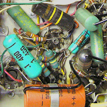
This picture's from an Ampeg B25B that came in for intermittent/scratchy performance and one broken channel. The channel 2 bass pot wouldn't turn at all. When I opened it up I found this dead bug and a bunch of what looks like it might have at one time been a clutch of eggs or something sprayed around the outside of the pot. Inside the pot there was another bug ground up and mixed with the pot lubricant which through some foul miracle turned into a sort of cement that held the pot stationary.

But that's not what this post is about.
The pot had to come out to be opened and cleaned. Taking resistors and axial caps off a board isn't so tough because they flex enough for you to heat the solder connection at one end of the component and gently pull that side out while the solder is still liquid. Then you just repeat for the other end.
Stiff components can be a pain though - especially ones held to the board at more than two points.
For this kind of job I frequently use this slightly modified desoldering iron. This style is just a regular iron with a suction tube attached to a hollow angled tip. You squeeze the red suction bulb and press the end of the iron against the joint. When the old joint becomes liquid you release the bulb and the solder is ostensibly sucked away.

The original tip has a fairly small opening so the only option for desoldering larger leads was to press the tip to one side of a joint, clear it and the do the other side. The seal against the board wasn't very tight this way. This meant that the suction wasn't great either so it usually would take a few passes to get enough solder off to free a joint.
To make the iron more useful for amp work I pulled the tip off and drilled it out from the back to 3/32 of an inch. Now the tip fits right over the ends of most components leads - even the fairly large ones on these Ampeg pots. With the lead fed up inside the tip the the whole joint is heated very evenly. Once the solder melts the opening of the iron can be pushed flush with the board. The tighter seal makes suction good enough to pull the solder off the joint, off the lead and out of the mounting hole in one fell swoop.

The desoldering tip goes right over the protruding lead. As soon as the old solder liquifies, release the bulb and the old joint is almost completely removed.
Part of the trick to having it work well is to tin the hole over with solder before using it. Tinning is just melting new solder onto the hot iron to form a molten solder coat over the tip. This protects the tip from corrosion and aids in the heat transfer. The old joints heat much more quickly this way. Most take only about 2 seconds. This is great becuse the shorter time and more even heat means less chance of damaging the board.
Here I'm melting a bit of fresh solder into the tip:

It's important to squeeze the suction bulb in before you start and then hold it there while you do the tinning - otherwise you'll just blow the solder out when squeeze the bulb before cleaning the joint. You can see below that the hole is completely filled with molten solder.

I find it's not necessary to re-tin the tip for every joint. I just do it when it starts taking a bit longer for the old solder joint to melt.
I ended up removing all the pots for good measure. Here are the joints from the treble pot. You can see the backplate for one of the disassembled rocker switches floating above suspended by it's leads.

These joints came clean with just one pass from the iron. The old pot pops right out without having to heat the joint again.

The mounting holes are generally clear enough that they don't have to be touched up at all before the pot goes back in - makes the whole business go a lot quicker.


 Posts
Posts