I'm going to start describing the Valve Junior Gain Matrix Mod with the physical side of the job. There are three gain stages in the Valve Junior. I'm installing one switch for each of these stages. Here's the chassis marked out for drilling the switch holes:

The switches will change the gain and frequency response by selecting and disconnecting the cathode bypass capacitors. Here is a front of chassis view the three switches installed:

And here they are from inside the chassis:

In the following post you'll see that the wires are color coded the wires to make it a bit easier to follow the wiring.
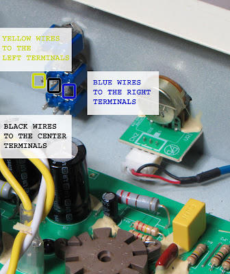
The yellow wires are for the "stock" configuration for each stage.
They connect to the left hand terminal of their respective switch.
The blue wires are for the "mod" value caps.
They connect to the right hand terminals.
The black wires are for ground and they connect to the center terminals:
Next up I'll show the actual circuit wiring and in the fourth I'll draw up a schematic for the mod.

The switches will change the gain and frequency response by selecting and disconnecting the cathode bypass capacitors. Here is a front of chassis view the three switches installed:

And here they are from inside the chassis:

In the following post you'll see that the wires are color coded the wires to make it a bit easier to follow the wiring.
The yellow wires are for the "stock" configuration for each stage.
They connect to the left hand terminal of their respective switch.
The blue wires are for the "mod" value caps.
They connect to the right hand terminals.
The black wires are for ground and they connect to the center terminals:

Next up I'll show the actual circuit wiring and in the fourth I'll draw up a schematic for the mod.


No comments:
Post a Comment