Friday, February 27, 2009
Ampeg Curiousites Part 5
Here's the EQ circuit card removed from an Ampeg B25B. If you look in the lower right you'll see a big rectangular component that looks sort of like a big ceramic capacitor:
If you look a bit closer you'll notice that it has seven leads - definitely not a simple capacitor or resistor. So what the heck is it? The answer can be found in the schematic.
Here's the preamp side of the schematic:
Have a look at the EQ part of the circuit - that's what we're looking at in the first picture above. The EQ section is highlighted below:
Zooming in on the lower of these you'll see the resistor / capacitor network that makes up the EQ section. There's a dotted line around the EQ section which I've highlighted in red. You'll notice that unlike R20, which is outside the dotted line, none of the capacitors and resistors within the dotted line have component numbers. That's because all of these components are contained within that little rectangular component in the first photo.
I've also highlighted the numbers that follow the dotted line. The numbers are 1-7 and correspond to the seven leads on the circuit card in the original picture.
These same little seven lead components are found in the tone circuits of a number of Ampegs. When these parts fail, the circuit has to be rebuilt with discrete components - it's an easy enough job if you just follow the schematic.
Thursday, February 26, 2009
Fedner Champion 600 12DW7 / ECC832 Mod Part 1 - Update
I'm focusing here on the 12DW7 / ECC832 partly out of curiosity and partly because it's half the work to rebias for the new tube. What is a 12DW7? Technical details can be found in the 12DW7 mod part 2.
The goal of the mod is to get a good bedroom level clean sound with a more useful range in the volume control. You can lower the gain and get more headroom by substituting a 12AT7,12AY7 or 12AU7 for the 12AX7. It won't be biased properly, but you may like the sound anyway and you're not going to hurt anything.
You can also plug a 12DW7/ECC832 in place of a 12AX7. A 12DW7 / ECC832 is one half 12AX7 and one half 12AU7. If you like the sound, try this mod to bias the lower mu half of the tube correctly.
THE UBIQUITOUS DISCLAIMER: AKAVALVE ASSUMES NO RESPONSIBILITY FOR THE SAFETY OF ANYONE IMPLEMENTING THESE INSTRUCTIONS. IF YOU ARE NOT FAMILIAR WITH SAFE PRACTICE IN HIGH VOLTAGE CIRCUITS, DO NOT ATTEMPT THIS YOURSELF.
All it takes is a 12K resistor jumpered in parallel with the stock 100K plate resistor R8 and a 1K resistor in parallel with the 1.5K cathode resistor R2. They're the two dark brown 3 watt IRC resistors shown in the middle of the picture.
The effect of putting 2 resistors in parallel is to reduce the overall resistance:
So the stock plate resistor in parallel with the additional 12K one gives a combined value of 10.7K for the plate. This greatly increases the current through the tube, which is what we need for a 12AU7.
With the current increased we need to change the bias of the stage to suit a 12AU7. With the stock resistor it will be running quite cold. The added 1K resistor in parallel with the stock 1.5K one yields a total resistance of 600 ohms.
If you're interested, the working through of the parallel resistance formula is covered in more depth in the Fat Boost Resistor Value post.
Here's a close up of the plate resistor. This jumpering method makes it very easy to remove the mod if you decide to go back to stock.
You can see below that the joint on the left hand of the plate resistor is not perfect - the solder hasn't flowed onto the lead of the original as completely as one would like. This is just for a listening test though so I didn't bother touching it up.
With this mod in place the amp is much cleaner and much quieter. It's important to note that you should NOT plug a 12AX7 back into the socket with the mod in place. A 12AX7 triode can't handle the amount of current that a 12AU7 triode can, so half of your 12AX7 will be toasted by the rebiased stage.
Wednesday, February 25, 2009
Fender Champion 600 Input Voicing Mod "Kit"
Instead of selling "kits" for the Champion 600 mods on this site, I'm putting together a series of posts with direct links to sources for the parts involved.
Below is a chart of capacitor values and -3dB points for the Champion 600 low input revoice mod.
This mod will work in a great number of amps with high and low inputs including the 5E1, 5F1 Champs and a host of other Fender Amps. You can find the the measured frequency response for a .012 uF cap in Part 2 of the mod post.
Clicking on any of the capacitor values in the chart should take you directly to a suitable part for the mod on the Mouser Electronics website. You can order directly from there.
If you have any questions about the parts links here, feel free to drop me an email.
Labels:
Capacitors,
Champ 5E1,
Champ 5F1,
Champion 600,
DIY,
Fender,
Mod Kits,
modding,
mods,
Part Value Charts
Sunday, February 22, 2009
Fender 5E1 / Champion 600 Coupling Cap Mod "Kit"
The stock capacitor in a Fender Champ 5E1 and 5F1 circuits is .022uF. This allows a great deal of bass through the circuit and the cap is frequently changed to restrict the low end and make the distortion a bit less muddy.
If you'd like to try changing this cap you can use the chart below to help select a value. In case you have trouble finding a place to purchase caps of the right value, each of the cap values in the chart has a link directly to a suitable part on the Mouser website.
Just click on any of the values and you'll see how it works.
The values in blue indicate that the cap values are in microfarads (uF). As the values get smaller I've switched to picofarads (pF) indicated in black.
If you are a bit foggy on the meaning of different capacitor values, see the capacitor values post.
The capacitor values here are good for a stock 5E1 Champ or a 5F1 Champ with a cathode bypass cap on the first stage (the frequencies shift a bit if that cap is not present and stock 5F1 champs don't have the bypass cap).
They'll also work in place of the tone stack in a Champion 600.
Labels:
Capacitors,
Math,
Mod Kits,
modding,
mods,
Part Value Charts
Saturday, February 21, 2009
Fender Champion 600 akavalve Mods
Since the blog format is a bit awkward to navigate through, I thought I'd make up a table of contents for my Fender Champion 600 Mod posts. First are the essential safety posts and then the mods listed in order of difficulty with the easiest ones first.
Discharging the filter caps:
Part 1
Part 2
Tube Upgrade:
New preamp and power tubes
Input Voicing Mod
Part 1
Part 2
Frequency Response Measurement
Input Mod "Kit"
Cap values for different frequency response and
Mouser Electronics Parts Links.
Presence Plus Mod:
The Presence Plus Mod
The Presence Plus "Mod Kit"
Cathode Bypass Mod
Part 1
This one includes a couple charts for bypass cap values
and their frequency response for both
the stock circuit and the Frondelli mod.
Part 2
This is the installation of the mod.
It uses large cap values
but smaller ones detailed in Part 1
could easily be substituted.
Part 3
This shows the measured frequency response
with the four different settings of the
cathode bypass lift described in part 2.
Tone Stack and Fat Boost Mods
Tone Stack Test
Installation Details and Frequency Response Graph
Explanation of the Fat Boost Mod resistor values
Tone Stack Bypass Cap Values (same as 5E1 Champ)
The 12DW7 / ECC832 mod
Part 1
Part 2
Miscellaneous:
Animated GIF of the disassembly
A look inside the chassis
Stock Speaker response measurement
Comparison of the Champ 5E1 and 5F1 schematics
Stock Output Transformer Measurement
I'm pretty sure that's all of them.
I'll add new ones to this list as I post them.
Part 1
Part 2
Tube Upgrade:
New preamp and power tubes
Input Voicing Mod
Part 1
Part 2
Frequency Response Measurement
Input Mod "Kit"
Cap values for different frequency response and
Mouser Electronics Parts Links.
Presence Plus Mod:
The Presence Plus Mod
The Presence Plus "Mod Kit"
Cathode Bypass Mod
Part 1
This one includes a couple charts for bypass cap values
and their frequency response for both
the stock circuit and the Frondelli mod.
Part 2
This is the installation of the mod.
It uses large cap values
but smaller ones detailed in Part 1
could easily be substituted.
Part 3
This shows the measured frequency response
with the four different settings of the
cathode bypass lift described in part 2.
Tone Stack and Fat Boost Mods
Tone Stack Test
Installation Details and Frequency Response Graph
Explanation of the Fat Boost Mod resistor values
Tone Stack Bypass Cap Values (same as 5E1 Champ)
The 12DW7 / ECC832 mod
Part 1
Part 2
Miscellaneous:
Animated GIF of the disassembly
A look inside the chassis
Stock Speaker response measurement
Comparison of the Champ 5E1 and 5F1 schematics
Stock Output Transformer Measurement
I'm pretty sure that's all of them.
I'll add new ones to this list as I post them.
Labels:
Champion 600,
DIY,
Fender,
Mod Kits,
modding,
mods,
Table of Contents
Fender Champion 600 Presence Plus Mod Kit
I've had a number of requests to provide kits for the mods described here. The components are generally quite simple - it's finding the sources and actual part numbers that may give people some trouble.
So instead of bagging up components, figuring out how to price them and sending them out, I'm going to try to provide links to Mouser for the exact parts needed for each of the mods.
This post is for the Presence Plus Mod.
If you're not making it switchable, the only part you need is the 16uF capacitor. Here's the link to the part on Mouser's website.
This is a lot easier for me than trying to make up "mod kits" and mailing them out. And it's cheaper for anyone interested in doing the mods too since you won't be paying for my time in the price of the kit. Let me know if it works well for you.
Saturday, February 7, 2009
Desoldering Tool for PC Board Mounted Pots
This picture's from an Ampeg B25B that came in for intermittent/scratchy performance and one broken channel. The channel 2 bass pot wouldn't turn at all. When I opened it up I found this dead bug and a bunch of what looks like it might have at one time been a clutch of eggs or something sprayed around the outside of the pot. Inside the pot there was another bug ground up and mixed with the pot lubricant which through some foul miracle turned into a sort of cement that held the pot stationary.
But that's not what this post is about.
The pot had to come out to be opened and cleaned. Taking resistors and axial caps off a board isn't so tough because they flex enough for you to heat the solder connection at one end of the component and gently pull that side out while the solder is still liquid. Then you just repeat for the other end.
Stiff components can be a pain though - especially ones held to the board at more than two points.
For this kind of job I frequently use this slightly modified desoldering iron. This style is just a regular iron with a suction tube attached to a hollow angled tip. You squeeze the red suction bulb and press the end of the iron against the joint. When the old joint becomes liquid you release the bulb and the solder is ostensibly sucked away.
The original tip has a fairly small opening so the only option for desoldering larger leads was to press the tip to one side of a joint, clear it and the do the other side. The seal against the board wasn't very tight this way. This meant that the suction wasn't great either so it usually would take a few passes to get enough solder off to free a joint.
To make the iron more useful for amp work I pulled the tip off and drilled it out from the back to 3/32 of an inch. Now the tip fits right over the ends of most components leads - even the fairly large ones on these Ampeg pots. With the lead fed up inside the tip the the whole joint is heated very evenly. Once the solder melts the opening of the iron can be pushed flush with the board. The tighter seal makes suction good enough to pull the solder off the joint, off the lead and out of the mounting hole in one fell swoop.
The desoldering tip goes right over the protruding lead. As soon as the old solder liquifies, release the bulb and the old joint is almost completely removed.
Part of the trick to having it work well is to tin the hole over with solder before using it. Tinning is just melting new solder onto the hot iron to form a molten solder coat over the tip. This protects the tip from corrosion and aids in the heat transfer. The old joints heat much more quickly this way. Most take only about 2 seconds. This is great becuse the shorter time and more even heat means less chance of damaging the board.
Here I'm melting a bit of fresh solder into the tip:
It's important to squeeze the suction bulb in before you start and then hold it there while you do the tinning - otherwise you'll just blow the solder out when squeeze the bulb before cleaning the joint. You can see below that the hole is completely filled with molten solder.
I find it's not necessary to re-tin the tip for every joint. I just do it when it starts taking a bit longer for the old solder joint to melt.
I ended up removing all the pots for good measure. Here are the joints from the treble pot. You can see the backplate for one of the disassembled rocker switches floating above suspended by it's leads.
These joints came clean with just one pass from the iron. The old pot pops right out without having to heat the joint again.
The mounting holes are generally clear enough that they don't have to be touched up at all before the pot goes back in - makes the whole business go a lot quicker.
Friday, February 6, 2009
Epiphone Valve Junior - Gain Reduction due to R6 and R7 in a Stock VJ
This post explains a particular part of the Epiphone Valve Junior circuit. If you're looking to reduce the volume and/or gain in your VJ, I started a series of posts for a gain reduction mod.
Here's a schematic for the stock Epiphone Valve Junior:
There is a voltage divider in the preamp to reduce the overall gain of the amplifier. R6 and R7 are 1 Meg resistors used to form the circuit:
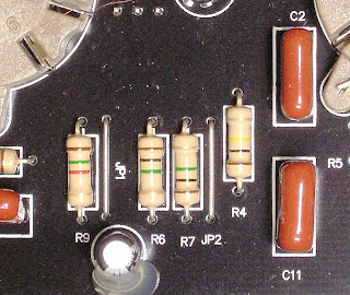
These two resistors are in series with the output feeding the next stage being taken at their junction. This a straight ahead voltage divider circuit. R6 and R7 are indicated in red on the schematic below Click on it to see it in full detail.
If you follow the math in the voltage divider posts, you'll see that with two resistors of equal value, as R6 and R7 are here, the voltage at the output will be 50% of the voltage at the input.
That would mean that with 2 Volts output from the first gain stage (V1) the voltage seen by the second stage (V2) would be just 1 Volt.
Things aren't quite that simple in the Valve Junior circuit though. If you look at the schematic you'll see that the 1 Meg volume pot is connected in parallel with R7:
So the voltage divider is really composed of three resistors - R6 in series with the total resistance of R7 and the volume pot in parallel.
Ok, so that's a bit more complicated. We really want just two resistances to calculate the voltage divider output. Fortunately two resistors in parallel can be treated as a single resistance. We can find the effective resistance of R7 and VR1 in parallel using the following formula:
If this formula seems too daunting, the Champion 600 Fat Boost Mod Resistor Values post goes though the details of how to apply it.
Using this formula you'll find that any two resistors of equal value connected in parallel will have a combined value of one half the value of a single resistor.
Incidentally, this is what guides the rule of thumb about connecting speakers in parallel (e.g. two 8 ohm speakers connected in parallel yields a 4 ohm load).
Here we're luck and the two are equal with R7 being 1 Meg and the end to end resistance of the volume pot being 1 Meg. One Megaohm is one million ohms. Half of one million is 500,000 ohms. One thousand ohms is one Kilohm, so the effective resistance of the two in parallel is 500 Kilohms or 500K.
Here is a modified schematic with the parallel resistance of R7 and VR1 shown a a single 500K component:
As far as the Valve Junior's functioning is concerned this simplified circuit is the same as the original circuit even though it doesn't indicate the actual physical components. This is what's called an equivalent circuit, and we use it to make the functioning of the circuit easier to comprehend.
So after all of that we have new values for the voltage divider. The top half is still the value of R6 - 1 Meg. The bottom half is now the equivalent resistance of R7 and VR1 in parallel, or 500k.
Using a form of the voltage divider formula we'll find that the output voltage will be about 30% of the input voltage. So with the 2 Volts input given in the example above, our output voltage should be 2 Volts times .3 which equals .6 volts.
You may notice that this .6 Volts is itself the input to another voltage divider - the volume pot itself. You can see how a pot acts a voltage divider in part 3 of the voltage divider post.
So after all that math, it's time for a reality check. Here the right hand meter is connected from the bottom of R7 to the top of R6 - effectively measuring the input voltage to the divider. The left hand meter is connected across R7 - effectively measuring the output voltage feeding the volume pot:
With enough signal applied to achieve 2 Volts from stage 1, the output voltage feeding stage 2 is .6 Volts - right in line with our calculations.
That's a gain reduction in the stock Valve Junior of about 10 dB. That means, of course, that eliminating the voltage divider by jumpering over R6 will result in a 10 dB increase in gain.
So now you know what that 1 Meg R6 is doing in your Valve Junior. Whether or not you want to keep it there is another story entirely.
Labels:
amp guts,
DIY,
Epiphone,
Math,
Measurements,
modding,
mods,
Resistors,
schematics,
Valve Junior
Subscribe to:
Posts (Atom)