Showing posts with label oddities. Show all posts

Sunday, June 7, 2009

Peavey Classic 30 Reverb Howl


This is another one from the slightly odd repairs file. Here's the reverb pan from a Peavey Classic 30 which came to me with a complaint that the reverb was "humming and feeding back".


Peavey Classic 30 reverb pan


When the reverb knob was turned up past 3 the amp made a pulsing howl which got louder the further the reverb knob was turned up.

Suspecting some magnetic coupling I took the reverb pan out of the amp, leaving the wires connected. By orienting the tank in different ways the problem could be greatly reduced but I couldn't get it to go away completely.

Disconnecting the RCA plug from the input jack on the reverb tank itself didn't affect the howl at all. Reconnecting it and disconnecting the outplug plug stopped it completely.

The quickest next step would be to swap out the tank to see if it was bad. Below is the Accutronics reverb tank part number 4EB2C1B printed on the tank itself:


Peavey Classic 30 Accutronics Reverb Part Number


Fortunately I happened to have another on of these around the shop. I plugged in the substitute and the amp was back to normal with a perfectly working reverb.

Now here's the odd part (and the reason I'm bothering to post such a run of the mill repair). I always try recheck once a repair is finished to make sure what I've done has actually fixed the problem. So for good measure I plugged the original tank back in. Now the amp worked fine with the original tank! Even though I'd plugged and unplugged the orginal tank a number of times somehow the act of plugging in the replacement tank caused the original tank to make a good electrical connection. I've seen oxidized or poorly toleranced plugs cause reverbs to stop working or have intermittent signal, but causing this howling was a new one on me. It just goes to show, it always a good idea to clean jacks and plugs even if you don't have a reason to suspect them.

Wednesday, April 29, 2009

Gregory Mark V / Gemini 700 practice amp


Once in a while a repair comes in that's a real surprise. This Gregory tube practice amp is one of them. When it was fixed up it really sounded fantastic. It's not as aggressive as most small amps. The treble is tamed and the distortion is fairly smooth and laid back and the clean sound is very sweet even at very low volumes.

I was really sorry when I had to give this one back!

Since the result is so nice, I thought I'd spend some time going though some of the oddities of the circuit.

Here's the schematic:


Gregory Mark V / Gemini 700 Schematic


There's a number of unusual things here.
The first is the input stage.

A run of the mill 12AX7 triode input would look
something like this:


triode input


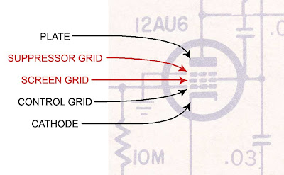
But the 12AU7 in this Gregory has two more elements in the preamp tube.

Here's what it looks like in the schematic:


12AU6 tube - pentode input


The plate, cathode and control grid are elements found in a triode tube.

I've labeled in red the additional elements the additional elements found in a pentode tube:


pentode tube elements


Since it has five elements instead of three, we call this tube a pentode. Pentodes are common as output power tubes. The EL34 is one. But pentode inputs on guitar amps are pretty rare birds (one example is the 6SJ7 in the early Fender Champs with the 5C1 circuit). The pentode input is certainly not sole contributor to the sound of the amp, but it makes me curious to try a 6SJ7 in the Champion 600.

I'll go through some more of the circuit in future posts (and hopefully get some pictures from the owner - I forgot to take some myself before I sent it back).


Friday, February 27, 2009

Ampeg Curiousites Part 5


Here's the EQ circuit card removed from an Ampeg B25B. If you look in the lower right you'll see a big rectangular component that looks sort of like a big ceramic capacitor:


If you look a bit closer you'll notice that it has seven leads - definitely not a simple capacitor or resistor. So what the heck is it? The answer can be found in the schematic.

Here's the preamp side of the schematic:


Have a look at the EQ part of the circuit - that's what we're looking at in the first picture above. The EQ section is highlighted below:


Zooming in on the lower of these you'll see the resistor / capacitor network that makes up the EQ section. There's a dotted line around the EQ section which I've highlighted in red. You'll notice that unlike R20, which is outside the dotted line, none of the capacitors and resistors within the dotted line have component numbers. That's because all of these components are contained within that little rectangular component in the first photo.


I've also highlighted the numbers that follow the dotted line. The numbers are 1-7 and correspond to the seven leads on the circuit card in the original picture.

These same little seven lead components are found in the tone circuits of a number of Ampegs. When these parts fail, the circuit has to be rebuilt with discrete components - it's an easy enough job if you just follow the schematic.


Wednesday, January 14, 2009

Reading Capacitor Values Part 1


Reading capacitors values from schematics or even parts lists can be confusing. There are a few basic rules to keep in mind that will make it a bit less daunting. First off the basic unit of capacitance is the farad. A farad is so large that you will never encounter a capacitor measured in farads. Most capacitors in tube amps are measured in microfarads. It takes one million microfarads to equal one farad. If a unit for a capacitor in a tube amp schematic is not specified the value is almost certainly microfarads (abbreviated uF). The rest will for the most part be picofarads (pF). I'll take some examples from the Fender Bassman 5F6A. Below is the complete schematic.


Here's an excerpt showing the 5F6A tone stack. The cap show in red is labeled .02-400. The first number indicates that the capacitance is .02 microfarads, the second number indicates the voltage rating, 400 volts in this case.
The treble cap is a much smaller value, .00025 microfarads. If you're looking though a parts catalog you are not likely to find a .00025 microfarad cap. That's because a cap of this size will more often be expressed in picofarads (abbreviated pF). There are on million picofarads in one micofarads. To find the value of a cap rated in micofarads in picofarads simply multiply by 1,000,000.


In this case .00025 microfarads x 1,000,000 = 250 pF.

Looking at the splitter of the phase inverter, there is a cap bridging the output of the inverter:


This cap is shown as at 47MMF. What does this mean? I've said already that the caps in tube amps are going to be fairly exclusively rated in microfarads (uF) or picofarads (pF). What does MMF mean?

In short, it is the same as picofards (pF). To understand why takes a bit of explanation. The abbreviation for "micro" is taken from the lower case of the Greek letter "mu".


Now you can see that the upper case "mu" looks just like an "M".
But what about the lower case"mu"?


Frequently you're not using the symbol for "mu" especially if you're typing. Convention has "mu" written as "u" so microfards is written uF. But in a way it's logical to think of the lower case "mu" as "m". This is why you'll sometimes see microfarads written as mF. Technically mF means millifarads (one thousandth of a farad) but since caps are not generally rated in millifarads you can safeley assume that if you see mF it is microfarads that is indicated.

MF techically means megafarad - one million farads. This is a value so ridiculously large that a cap this large could not even begin to be manufactured. If you see MF you can also assume microfarads (uF).

So the MMF from above can be considered to be mmF or micromicrofarads. "Micro" means "one millionth" or "divided by 1,000,000). A picofarad is a microfarad divided by 1,000,000. So saying micromicrofarad is really the same as saying picofarad.


So to sum up:

The majority of tube amp caps will be indicated in microfarads (uF, mF, MF) and picofarads (pf, mmf, MMF). Occasional you will see nanofarads (nF). A nanofarad is simply one thousanth of one microfarad or one thousand picofarads.

If a unit for a capacitor in a tube amp schematic is not specified the value is almost certainly microfarads.


Saturday, December 6, 2008

Ampeg V4 curiousities part 1


A quick tour of the power supply end of the underside of the circuit board and a look at the unusual plate resistors.