Thursday, November 12, 2009

Drawing up a component layout from a tube amp schematic


I'm building up a low wattage tube practice amp roughly
based on an old Gregory Gemini 700 / Mark 5.
Since the circuit is pretty simple, the process may help you to learn
how to translate a schematic diagram into an actual tube amp layout.
Here's a schematic for the No. 2 version of the Gregory:


So how do I get from that schematic to this:


It's not too difficult if you take it one step at a time.
I'll show you loosely how I approached it for this one.

First have a look at the schematic and try to divide it into functional blocks.
That will keep you from getting confused as you go along.
It'll also be much easier to troubleshoot if everything doesn't work on the first try.

Below I've boxed the preamp stage in red, the tremolo section in orange,
and the power and output section in black:


Now you need to figure out what the components are actually
going to be physically and electrically attached to.
I find that some kind of tagboard or turret board makes the planning
and subsequent wiring neat and easy to follow.

I picked this board from Antique Electronic Supply.


Now on a sheet of graph paper I drew in the components
for the individual amp stages in colors that match
the sections I indicated on the schematic.
Then I drew in all the connections that would need
to be made according to the schematic.

At this point check and double check you work.

This drawing is done imagining the tagboard oriented vertically.
Each of the rectangles relates to one resistor or capacitor in the circuit
and the lines represent connections between them.

I do this stuff pretty regularly, so you'll see I'm not super fussy about neatness or corrections.
You'd want to be a bit more careful yourself until you can rely on your instincts to catch errors:


There also components which will not be mounted on your board
(control pots, tube sockets, transformers etc).
I've been lazy here and only indicated the pots.
They're in green on my hand drawing and circled in green on the schematic below.
You should probably be careful to include them all if you haven't done this before.
Thoroughness will pay off in the end.


Now turn the layout drawing in the same direction as the tag board
and you're ready to start soldering:


I install all the components first and then move onto the connections.
Here are the caps and resistors installed on the board:


And here's the board with the electrical connection in place:


Now all that's left is to install the board and make the connections
to the chassis mounted components and fire it up to see if it works!


If you're paying very close attention, you'll notice that my layout
drawing doesn't match the schematic drawing exactly
(and the board doesn't exactly match the drawing).
I've made some changes as I been working on these amps
but I haven't drawn up a revised schematic yet.
The one here should serve well enough for the example though.






Monday, November 2, 2009

Low Wattage Tube Practice Amp - Plywood Mockup


I've been working out a circuit for a low wattage tube practice / recording amp inspired by the Gregory Gemini 700 / Mark V . This weekend I took a break from the electronics and built a plywood mockup for the cabinet to see how I liked the size feel of it at home. Here it is in my living room:


low wattage tube amp plywood mockup


I'm going to give it some kind of tilt back legs. Here it's just propped up on an Altoids tin to see how it looked tipped back a bit. I'm pretty happy with the size of it in the house. Once I wire up the chassis I can see how it sounds with a speaker in there. If all's well I'll build up the cabinet in real wood with real joinery.


Here it is with the cat for scale (and because, oddly, they match):


low wattage tube practice amp with curious cat


Our cat is a mammoth - 14 lbs fit and trim - so the cab is actually a bit bigger than it looks. I'm planning to put a Weber 8" in there, but there's enough room for a 10" in case the 8" doesn't cut it. The baffleboard is designed to be easy to remove so I can try a few different speakers without a lot of fuss. I may even try a pair of Weber 6's in there for kicks.


Wednesday, October 21, 2009

Epiphone Valve Junior - the Gain Matrix Mod Part II


I'm going to start describing the Valve Junior Gain Matrix Mod with the physical side of the job. There are three gain stages in the Valve Junior. I'm installing one switch for each of these stages. Here's the chassis marked out for drilling the switch holes:


Valve Junior Gain Reduction Mod - chassis marked for drilling


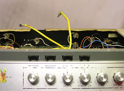
The switches will change the gain and frequency response by selecting and disconnecting the cathode bypass capacitors. Here is a front of chassis view the three switches installed:


Valve Junior Gain Reduction Mod - switches installed


And here they are from inside the chassis:


Valve Junior Gain Reduction Mod - switches from inside chassis


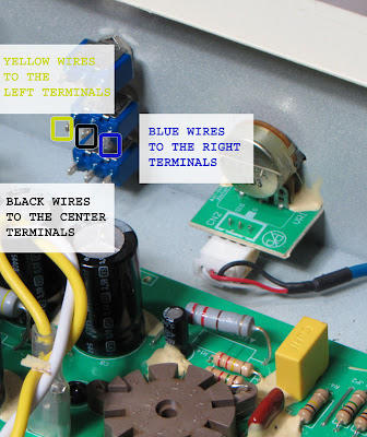
In the following post you'll see that the wires are color coded the wires to make it a bit easier to follow the wiring.
The yellow wires are for the "stock" configuration for each stage.
They connect to the left hand terminal of their respective switch.
The blue wires are for the "mod" value caps.
They connect to the right hand terminals.
The black wires are for ground and they connect to the center terminals:


Valve Junior Gain Reduction Mod - wire color coding


Next up I'll show the actual circuit wiring and in the fourth I'll draw up a schematic for the mod.


Tuesday, October 20, 2009

Champion 600 Speaker Upgrade Comparison


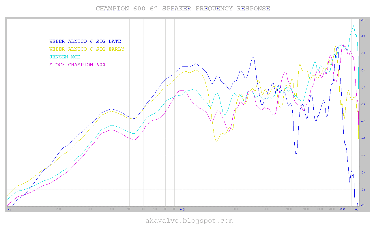
I installed four different speakers in my Champion 600 and ran some frequency response sweeps for the sake of comparison.*

What I saw in the graphs pretty much confirmed what I heard in each of them.

First the stock speaker compared to a Jensen Mod:


Champion 600 Stock Speaker vs Jensen Mod


Just as my ear was telling me - the Jensen is a touch more efficient and a touch smoother but they really didn't sound all that different. I found the difference to be hardly worth the upgrade cost.

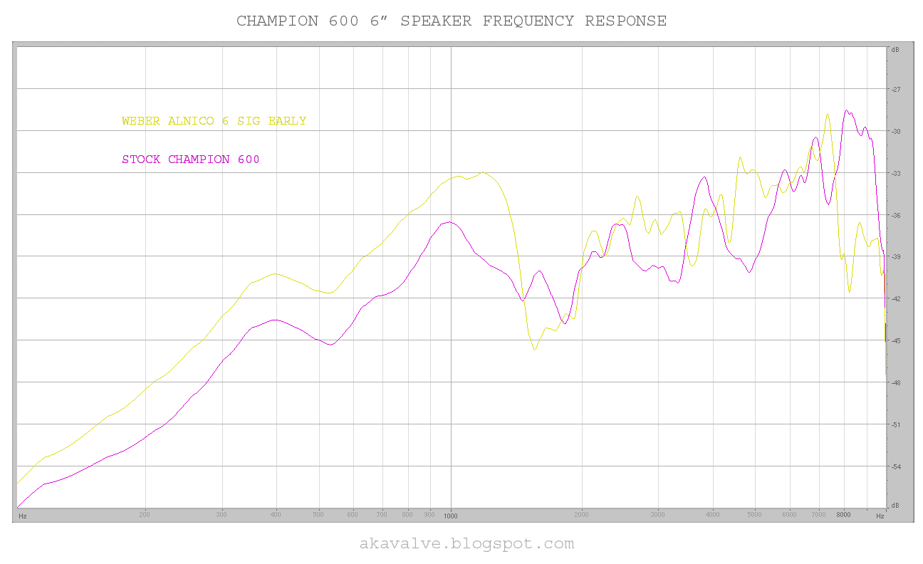
Here is the Weber alnico with a late breakup cone compared to the stock Champion 600 speaker:


Champion 600 stock speaker vs Weber alnico late break up ribbed cone


Notice that the Weber late breakup alnico is a good bit more efficient than the stock speaker up to about 3K, where it drops off dramatically. This probably accounts for some people experiencing the Weber as dark sounding. What isn't evident from the graph is that in addition to the increased bass response the Weber is more able to handle the bass so it doesn't fart out the way the stock speaker does.

The next graph is interesting. It compares the Weber late break up ribbed cone to the Weber early break up smooth cone:


Weber alnico speaker comparison - late break up ribbed cone vs early break up smooth cone


They're pretty similar in the bass but in the upper mids and treble they're very different. So in addition to the breakup characteristics they have quite different upper range response. Personally I prefer the smooth cone sound - it sounds a bit more vintage to my ear. The ribbed cone sounds tighter and more modern. They both sound great though and are both worth the upgrade.

Here is the smooth cone Weber compared to the stock speaker:


Weber smooth cone early break up alnico compared to the Fender Champion 600 stock speaker


It look much more like the original in the treble response. Kind of like the stock speaker with increased bass and mids (and better bass handling).


Here's plots for all four speakers on the same graph - just for ease of comparison:


Frequency response of all four Champion 600 speakers


Incidentally, I found that the stock grill cloth really does flap around at higher volumes making some nasty farting and flapping along with the low notes. I cut mine out when I cut down the baffleboard for the Weber speaker installation and am looking for something to replace it with.


* These graphs are for the sake of comparison between the speakers. Since they aren't anechoic chamber tests the graphs include the room effects so don't pay to much attention to each tiny peak and dip. They don't show isolated speaker response but work fine to illustrate how the speakers differ from each other under the same room conditions.


Monday, August 3, 2009

Epiphone Valve Junior - the Gain Matrix Mod


Here's a gain reduction mod I recently completed on an Epiphone Valve Junior. The owner was looking for less volume and less gain. This mod has 3 switches each with three positions:


Epiphone Valve Junior gain reduction with the gain matrix mod


With all the switches set to the left the amp is stock. Flipping a switch to the center position reduces the gain by taking the cathode bypass cap for that stage out of the circuit.

Flipping it all the way to the right switches in a different value cap for the cathode bypass. In the right position the upper two switches act as differently voiced bright/body switches and the bottom one acts as a deep switch.

The amp can now be made quiet enough to be used at home. It can be cleaned up for less gainy sounds and brightened for more clarity. And it can be quickly returned to stock if you miss that muddy sound it had when it was new. The various combinations of three switches give a total of 26 alternate voicings.

I shot pictures of this mod but I haven't written up a whole description. If anyone is interested in seeing the whole process, let me know in the comments section of this post and I'll put the details together.


Sunday, July 26, 2009

How to fit a Weber alnico speaker into a Champion 600 with a JJ 6V6


The original owner of this Champion 600 decided to move to a larger amp . I'd put so much time into the mods that I decided to buy it from him to try a few things he hadn't been quite ready to spring for himself. The first was to try a couple Weber 6" alnico speakers. If you'd like to see the index of mods I've done on this little amp, it's here. This is the back of the amp with the "early breakup" smooth cone alnico speaker installed:


Weber Alnico speaker in a Champion 600 with a JJ Tesla 6V6


Notice the nice bit of clearance between the magnet and the JJ Tesla 6V6. In a stock Champion 600 cabinet the big magnet on the Weber Alnico barely fits if you have a larger bottle 6V6 like the JJ in there. To get the clearance I moved the baffleboard over.

The baffleboard that is in there already has a bit of play. If you unscrew it you can slide it to the left and remount it. That'll give you just enough space to get the speaker in without it touching the tube. Here's the front of the amp with the new Weber installed:


Moving the baffleboard in a Fender Champion 600 allows you to fit the large magnet on a Weber alnico next to a large 6v6


It's easy to see the shifted speaker because I've also removed the grill cloth. The original cloth is so thick that it causes some farting out on low notes. It made a good bit of difference to get rid of it. I plan to find something appropriate to replace it with once my speaker experiments are done.

The stock baffleboard won't shift quite as far as you see in the photo above. It was close enough but I wanted to have a healthy bit of space between the speaker magnet and the power tube so I cut the baffleboard down by a half an inch and slid it over even further. You can get away with this because the TV style front actually covers a good bit of the baffleboad. I used silver sharpie so the cut and drill markings would be clear in the picture:


the baffleboard in a Fender Champion 600 marked for cutting


I marked off one half inch from the right edge and marker centers for new mounting holes a half inch to the left of the originals. That's about 13mm for people sensible enough to be on the metric system.

Here's the baffleboard cut down to size and with the new mounting holes drilled out.


cutting down the baffle board in a Fender Champion 600


If you do this yourself it's important to note that this view is from the FRONT of the baffleboard. If you do the same thing looking at the back you'll move the speaker in the wrong direction!

Currently on hand I have the stock Champion 600 speaker, a Jensen Mod and two Webers (early and late breakup). I'll post frequency response and sensitivity comparisons in the next round.


Friday, July 24, 2009

Where is the dangerous voltage in a tube amp?


"UNPLUG YOUR AMPLIFIER AND DISCHARGE THE FILTER CAPS BEFORE YOU START WORK INSIDE A TUBE AMPLIFIER. THERE ARE LETHAL VOLTAGES INSIDE THAT CAN KILL."

Everyone who's started working with tube amps has heard that a hundred times. And it's absolutely essential advice. But obviously you need to turn the amp back on to test your work. Is it safe to run the amp while it's out of the cabinet as long as you're don't poke around inside?

Not necessarily. Dangerous voltages can appear where you least expect them - either through circuit design or component failure.

Here's an Ampeg V4 / VT22 that's in for a tune up. The reverb pan for these amps is under the top cover and if you're doing extensive work it's much more convenient to unplug it. Here your can see the RCA cables that connect to the pan dangling above the chassis:


Ampeg V4 VT22 reverb leads disconnected


Now normally one doesn't associate reverb leads with high voltages, so you might be inclined to let them hang where ever they may. Lets take a look at what happens when the amp is switched on:


Ampeg V4 VT22 dangerous voltage
The meter here is measuring the DC voltage between the center pin of a reverb lead and the amplifier chassis. It's showing 0.013 volts. That wouldn't shock a flea. Nothing wrong there. What happens when the standby switch is thrown into the operate position?


dangerous voltage on a tube amp reverb lead with standby switch in operate


181 Volts! You'll be glad if that's not dangling out the back of the chassis touching the screwdriver you're about to pick up! This voltage isn't there for all that long. The sequence below shows 1 second intervals.


high voltage on Ampeg V4 VT22 reverb leads drops fairly quickly to a safe level


It drops from 181.2 to 104.7 in just a couple seconds. In 15 seconds the voltage drops to 12 volts and keeps dropping from there. Because of the grounding scheme in the standby circuit of the V series Ampegs high voltages appear all over the amp in places you wouldn't usually expect them - even when the amp is in standby!

The point is, never assume that there is no voltage at some point in a tube amplifier just because there's no reason for it to be there. If you're are unsure, check with your meter. If your meter says it's safe, don't assume it's always safe. Things change. Never let wires dangle unprotected from the chassis. You never know what kind of surprise they might have in store. And always work with one hand behind your back. In case you do make a mistake the current is less likely to go straight through your heart.