Wednesday, April 29, 2009

Gregory Mark V / Gemini 700 practice amp


Once in a while a repair comes in that's a real surprise. This Gregory tube practice amp is one of them. When it was fixed up it really sounded fantastic. It's not as aggressive as most small amps. The treble is tamed and the distortion is fairly smooth and laid back and the clean sound is very sweet even at very low volumes.

I was really sorry when I had to give this one back!

Since the result is so nice, I thought I'd spend some time going though some of the oddities of the circuit.

Here's the schematic:


Gregory Mark V / Gemini 700 Schematic


There's a number of unusual things here.
The first is the input stage.

A run of the mill 12AX7 triode input would look
something like this:


triode input


But the 12AU7 in this Gregory has two more elements in the preamp tube.

Here's what it looks like in the schematic:


12AU6 tube - pentode input


The plate, cathode and control grid are elements found in a triode tube.

I've labeled in red the additional elements the additional elements found in a pentode tube:
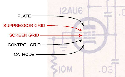


pentode tube elements


Since it has five elements instead of three, we call this tube a pentode. Pentodes are common as output power tubes. The EL34 is one. But pentode inputs on guitar amps are pretty rare birds (one example is the 6SJ7 in the early Fender Champs with the 5C1 circuit). The pentode input is certainly not sole contributor to the sound of the amp, but it makes me curious to try a 6SJ7 in the Champion 600.

I'll go through some more of the circuit in future posts (and hopefully get some pictures from the owner - I forgot to take some myself before I sent it back).


Monday, April 27, 2009

Trippy Reverb Trick for Two Channel Fender Amps


This is a trick to get a deep and spacey reverb sound out of most 2 channel Fender Amps.

Here's the set up with the "Normal" channel jumpered to the "Vibrato" channel:

Fender Trippy Reverb Trick
Generally people DON'T jumper channels on their Fender amps because
the two channels are phase reversed*. This means the two channels cancel each other out.
So instead of getting more volume from the second channel
when you turn it up, you get less.

This trick takes advantage of that cancellation to get rid of a lot
of the straight guitar sound leaving mostly reverb.


----Video Quality Disclaimer----

The video makes it sound like the amp has loads of buzz.

It doesn't actually - it's the foolish AGC
circuit on the camera.

Soldier through and you'll get the basic idea though.

--------

This video shows the basic setup:


The sound on the video will give you the "how to" but doesn't capture the depth of the reverb, so I suggest you try it yourself to hear what it sounds like in person. It's much more dramatic.

You can also toy with the tone control settings to get more variations from the reverb sound.
It can get pretty wacky with some tweaking (and it can get loud quick so be careful).


* Technically they are "reversed polarity" or "180 degrees out of phase".
Though incorrect "phase reversed" or "out of phase" are the more colloquial usage
and they're the ones you're more likely to hear in music circles.


Are these two resistors different?


One of the first steps you'll read in any set of tube amp troubleshooting instructions is "visual inspection". It just means looking over the components for any obvious signs of stress. Here I've stuck two 100K resistors in a piece of foam for the sake of comparison.


Fender '65 Twin Reissue failed plate resitor


Looking at the two 100K resistors pictured an astute observer might notice the slightly darker midsection of the upper resistor. It's fairly subtle here and even more so when it's still in the circuit, not positioned right next to a normal looking one.


These resistors are plate resistors taken from a Fender '65 Twin Reissue that came in with a broken Normal channel. The resistor that shows slight signs of overheating was completely open. It was passing no current at all, effectively shutting off the tube. It might as well have not have even been in the circuit. I replaced it to get the channel working again.


So why did I take out both resistors? Well the second one is actually completely open as well, it just doesn't happen to show any visible signs of fatigue.


That's the trick with visual inspection. It's a very good first step. But troubleshooting effectively means knowing how to use your meter to see for you. Parts can fail in many ways that you never have any hope of catching with your eyes.


Saturday, April 18, 2009

Fender Champion 600 Preamp Bias Part 6a


Sound is change. That is, what we perceive as sound is our ears registering variations in air pressure. Air pressure is changing with the weather all the time. But what our ears are sensitive to are very quick fluctuations - between 20 and 20,000 times a second. If there are variations in air pressure back and forth between a higher and lower pressure at 440 times a second what we hear is an "A" note ("A 440" to be specific). It doesn't matter what the barometric pressure is that day, what our ears register as sound are the changes.


For an amplifier to pass "sound" the signal inside it has to be electrically equivalent to these fluctuations. You can think of it as an electrical picture of the sound we hear. The changes in air pressure have corresponding "electrical pressures" (voltages) inside the amplifier. When the output voltage of the amplifier is applied to the speaker the movement of the speaker produces variations in air pressure which we perceive as sound. If a voltage varies back and forth between 1 volt and -1 volt at 440 times a second, the speaker will vibrate at that same rate and we hear an "A" note.


I mention this in order to introduce the concept of alternating current (AC) which will be essential in completing our discussion of preamp bias.


To uderstand AC let's look first at a graph of direct current (DC) voltage over time:


DC (Direct Current) voltage over time


If you were to measure the voltage at an instant it time your reading would be the same at 1 second as it would be at 2 seconds, 3 seconds or 4 seconds. That's the definition of DC. No change.


Now imagine a voltage that rises and falls as time passes:


AC (Alternating Current) Voltage over time


If you could measure the voltage at an instant of time your reading would depend on what instant in time you chose. At 1 second the voltage would be 2 volts.


instantaneous voltage at 1 second


But a second later it would be 1 volt:


instantaneous voltage at 2 seconds


We don't talk about AC in terms of "+1 volt at 2 seconds". It's really not practical to measure a voltage at an instant in time. Instead we have a few different ways of quantifying an AC voltage. The one we'll use here is probably the easiest to understand. It's called "Peak to Peak". It's simply a measure of how much the voltage changes from it's lowest to it's highest point:


Peak to Peak AC Voltage


Just subtract the lowest voltage from the highest voltage and you have the Peak to Peak (abbreviated P-P). The above example is pretty straightforward. Since the lowest voltage is zero the P-P voltage is the same as the voltage at the high point - 2 volts.


Let's look at a slightly more complicated example.


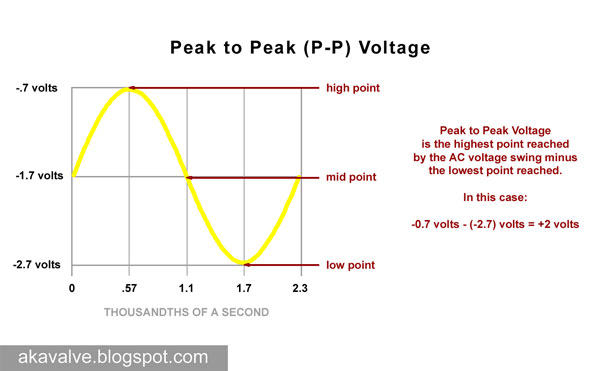
Let's make the highest voltage a negative value, -.7 volts. The lowest value will have to be lower than that, or even more negative. Let's make it -2.7 volts:


Peak to Peak Voltage with the swing centered around the 12AX7 bias point


The difference between the two is 2 volts, the same as in our first example.


You may have noticed anther change in this example. I've changed the time scale on the bottom of the graph. Instead being 0 to 4 seconds it's 0 to 2.3 milliseconds. The graph shows one complete cycle of the sine wave, going from the mid point to the high peak, to the low peak and returning to the mid point. In the previous example one cycle took 4 seconds to complete. In this one it takes 2.3 milliseconds or .0023 seconds - much quicker.


If one cycle takes only .0023 seconds how many cycles happen in one second?
It's 1 divided by .0023. Rounding up that's 440 Hz - the "A" note mentioned in the opening of this post.


We'll get to why I chose those voltages and what it has to do with our whole bias investigation in Part 6b.