Sunday, July 26, 2009
How to fit a Weber alnico speaker into a Champion 600 with a JJ 6V6
The original owner of this Champion 600 decided to move to a larger amp . I'd put so much time into the mods that I decided to buy it from him to try a few things he hadn't been quite ready to spring for himself. The first was to try a couple Weber 6" alnico speakers. If you'd like to see the index of mods I've done on this little amp, it's here. This is the back of the amp with the "early breakup" smooth cone alnico speaker installed:
Notice the nice bit of clearance between the magnet and the JJ Tesla 6V6. In a stock Champion 600 cabinet the big magnet on the Weber Alnico barely fits if you have a larger bottle 6V6 like the JJ in there. To get the clearance I moved the baffleboard over.
The baffleboard that is in there already has a bit of play. If you unscrew it you can slide it to the left and remount it. That'll give you just enough space to get the speaker in without it touching the tube. Here's the front of the amp with the new Weber installed:
It's easy to see the shifted speaker because I've also removed the grill cloth. The original cloth is so thick that it causes some farting out on low notes. It made a good bit of difference to get rid of it. I plan to find something appropriate to replace it with once my speaker experiments are done.
The stock baffleboard won't shift quite as far as you see in the photo above. It was close enough but I wanted to have a healthy bit of space between the speaker magnet and the power tube so I cut the baffleboard down by a half an inch and slid it over even further. You can get away with this because the TV style front actually covers a good bit of the baffleboad. I used silver sharpie so the cut and drill markings would be clear in the picture:
I marked off one half inch from the right edge and marker centers for new mounting holes a half inch to the left of the originals. That's about 13mm for people sensible enough to be on the metric system.
Here's the baffleboard cut down to size and with the new mounting holes drilled out.
If you do this yourself it's important to note that this view is from the FRONT of the baffleboard. If you do the same thing looking at the back you'll move the speaker in the wrong direction!
Currently on hand I have the stock Champion 600 speaker, a Jensen Mod and two Webers (early and late breakup). I'll post frequency response and sensitivity comparisons in the next round.
Friday, July 24, 2009
Where is the dangerous voltage in a tube amp?
"UNPLUG YOUR AMPLIFIER AND DISCHARGE THE FILTER CAPS BEFORE YOU START WORK INSIDE A TUBE AMPLIFIER. THERE ARE LETHAL VOLTAGES INSIDE THAT CAN KILL."
Everyone who's started working with tube amps has heard that a hundred times. And it's absolutely essential advice. But obviously you need to turn the amp back on to test your work. Is it safe to run the amp while it's out of the cabinet as long as you're don't poke around inside?
Not necessarily. Dangerous voltages can appear where you least expect them - either through circuit design or component failure.
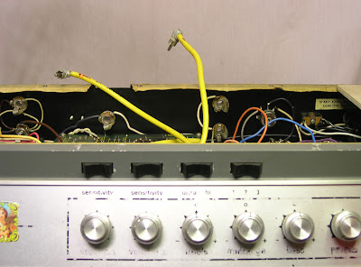
Here's an Ampeg V4 / VT22 that's in for a tune up. The reverb pan for these amps is under the top cover and if you're doing extensive work it's much more convenient to unplug it. Here your can see the RCA cables that connect to the pan dangling above the chassis:
Now normally one doesn't associate reverb leads with high voltages, so you might be inclined to let them hang where ever they may. Lets take a look at what happens when the amp is switched on:
The meter here is measuring the DC voltage between the center pin of a reverb lead and the amplifier chassis. It's showing 0.013 volts. That wouldn't shock a flea. Nothing wrong there. What happens when the standby switch is thrown into the operate position?
181 Volts! You'll be glad if that's not dangling out the back of the chassis touching the screwdriver you're about to pick up! This voltage isn't there for all that long. The sequence below shows 1 second intervals.
It drops from 181.2 to 104.7 in just a couple seconds. In 15 seconds the voltage drops to 12 volts and keeps dropping from there. Because of the grounding scheme in the standby circuit of the V series Ampegs high voltages appear all over the amp in places you wouldn't usually expect them - even when the amp is in standby!
The point is, never assume that there is no voltage at some point in a tube amplifier just because there's no reason for it to be there. If you're are unsure, check with your meter. If your meter says it's safe, don't assume it's always safe. Things change. Never let wires dangle unprotected from the chassis. You never know what kind of surprise they might have in store. And always work with one hand behind your back. In case you do make a mistake the current is less likely to go straight through your heart.
Wednesday, July 22, 2009
Federal Tube Limiter Release Time Adjustment
The top unit in the picture here is a big old Federal tube limiter from Kissy Pig studios.
This unit was new to Kissy Pig. It certainly looked great but it didn't sound nearly as nice. That's because it was designed and built for the US military for use as a broadcast limiter to prevent overmodulation of communications broadcast signals. When transplanted to the modern recording studio it's got a couple of problems. First is that if it's just plugged into the patchbay it has way too much gain and the limiter triggers very early. This is because it was designed for the 600 ohm world when most audio equipment had a 600 ohm impedance on both the input and the output. Interfacing directly with the high input and low output impedance of modern gear can cause operating level and frequency response problems. I strapped a 620 ohm resistor strapped across the output and made a cable with 10K resistors in series with each of the legs of the input to fix the impedance mismatch which in turn cured the operating level problem.
It had a second issue that made it pretty unusable in a studio situation. The release time was very long. According to the manual it was 2 seconds. That's because the Federal limiter was designed to react slowly - to keep the level of a speaking voice under control. That makes the device sound pretty weird when you put something like drums through it. The first hit sounds great when the limiter kicks in. But since the release time is so long you don't hear the limiting kick in again until it's had a chance to recover. So if there was more than a second between drum hits it sounded pretty great. Otherwise it just sucked the volume down and kept it there. Not so good.
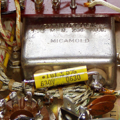
Fortunately the circuit is not very complex. There is one capacitor that can be changed to adjust the time constant for the limiter circuit. It's a 1.0 uF Micamold cap. It's the the huge shiny silver box shown below:
It's C1 in the schematic (click on the schematic for a larger version):
I removed the lead form the left hand terminal of the original cap and used that lead to connect a new cap from the tube cathode pin to the base of the cathode resistor. It actually physically connected to the other terminal of the original cap, but that made a more convenient connection point. With the other lead disconnected the cap is out of circuit so there's no reason not to.
We tried a few different values in studio to hear what sounded best and ended up with 1/10th of the original value. That's the one you see in the circuit now. It's a Mallory 150 series .1 uF cap. Now the unit sounds great and is operating at normal levels. While I was there a shot pictures of the entire manual. If there's anyone looking for a copy, email me and I'll send it along as a PDF.
Monday, July 20, 2009
An angled desoldering tool for cleaning tube socket terminals
Removing components and solder from tube socket tabs is not difficult. But it's a tedious business. If you're removing a lot of components you'll be glad for anything that speeds the process up. Here's a standard solder sucker or solder pump:
It's a common tool used to suck molten solder away from a solder joint. It's spring loaded inside. After it's cocked, pushing the black button releases the internal plunger and causes a vacuum effect at the tip to suck solder away into the body of the pump. It works well in plenty of situations but frequently the flat tip doesn't quite fit the bill. I keep a collection of desoldering tools suited for specific jobs (here's another one I modified for use for PC board mounted pots). On this one I've cut away part of the tip for use at tricky angles. Here's the stock tip and the angled one:
The angled tip is hugely helpful for getting a good seal against the old solder joint on a tube socket terminal. Here it is pressed against one side of the solder joint with the soldering iron heating the joint from the other side:
Note the angle of the tip. In tight quarters it's impossible to get a straight tip to sit this snugly against the tube socket tab. With a nice tight seal against the joint the terminal comes clean with just one activation of the pump:
This may seem trivial, but when you have enough joints to do it saves serious amounts of time. There are around 50 joints for me to desolder and clean on this Ampex 601 rebuild. Futzing around with awkward positioning of the desoldering pump makes for a poor seal and it can easily take a half dozen shots to clean the joint out well in a cramped chassis. If you fiddle with each joint for 2 or 3 minutes you could be spending a couple hours just sucking the solder out. Getting the remaining wires and component leads off of the terminals without damaging them can still be fiddly. But having the old solder removed quickly speeds the process up immensely and gets you on to the interesting parts of the work.
Sunday, July 12, 2009
Is the Ampex 600 / 601 a good vintage tube mic preamp bargin?
The Ampex 600's and 601's were mono reel to reel decks with tube electronics common to many units of the time. Not many people have a use for a mono tape deck these days, but these units have both a mic and a line input jacks and a line out. So they're being bought as a way to get a real tube microphone preamp for not much dough. Not a bad idea, but you do need to be pay attention to what you're actually getting for the money. A tube mic pre requires an input transformer to work well with modern low impedance microphones. In vintage tube mic pres this transformer frequently plugs into an octal socket like the ones used for large power tubes. Here's the empty socket from an Ampex 601 that came in for a recapping job:
Good quality input transformers don't come cheap. If this socket is empty, think of spending just shy of $100 to put a transformer in there. Here's what the socket looked like in this unit when it came to me:
That's how the input transformer plugs into the socket. Here's the base of the part that came in this Ampex:
The base looks just like an octal power tube and it plugs in in the same way. Let's look a little closer at this one. Here is the piece standing on it's base:
Here I've popped off the metal shield so you can see the transformer windings:
If you can't make out the windings, don't be concerned. There aren't any. This is a simple dummy plug inserted into the transformer socket. Since transformers are so expensive most of these Ampex 600 and 601 tape decks shipped with no input transformer. All they had was this jumper plug. This was cheaper and worked fine with the high impedance microphones designed to work with this sort of input back in the day. It won't work well with microphones you are likely to own now though. So if you're thinking of buying one of these vintage tube pres for recording ask if there is a microphone input transformer before you make an offer, and remember that you're going to be spending close to an extra $100 if there's not one.
Wednesday, July 8, 2009
Are tubes with broken bases still good?
Here's a pair of EL34's that came out of a very unhealthy Traynor YVM-1. Take a close look and compare the bases:
The black cylinder in the center of one of the tube bases is broken off and the bottom of the glass envelope is poking through the bass. This central post is commonly called the key, guidepost or locator pin. It's a bit easier to see here:
So is there anything wrong with using a tube with that black center piece broken off?
Well, yes and no. It doesn't have any electrical function, but you do need to be careful. To explain why I'll start with the bottom of the unbroken tube:
You may be able to make out the numbers labeling the pins, You can also see that the center piece is not a perfect cylinder, it has a small protrusion between pins 1 and 8. I've diagramed both in red here in case it's not completely clear from the photo:
That little protrusion is meant to lock into the groove in the tube socket. With it in place the tube can only plug in in one orientation.
Someone must have tried to force a tube into this socket in the wrong orientation. You can see a chip in the socket made by the tubes key as it was forced in:
My guess is that that is what broke the key off of this tube:
With the key broken off you don't have to fiddle around and align the tube. I can fit it in 8 different ways. That certainly makes things easier. Let's look at the connections made when the tube is inserted. Here's the same socket rotated 180 degrees so the key slot point down:
Now I've overlayed the schematic diagram for an EL34 to show how it's internal elements are connected to those pins.* The black block at the bottom of the diagram indicates the key. I've lined that up with the groove in the socket to show a properly inserted tube. I've also labeled the socket connection with ballpark voltages you would expect to find on those sockets.
Now imagine that the tube is inserted so that the key in the diagram lines up with the chip made in the socket when the tube was forced in. The voltages present on the sockets stay the same the tube elements that those voltages are connected to would be different. I've rotated the tube diagram below to illustrate the point:
The most obvious problem here is that the 445 volts on socket #4 is now connected to pin #7 on the tube.
Inside the tube pin #7 is pin # 2 by the heater element. That effectively connects the 445 volts on socket #4 directly to socket #2. In the amplifier circuit socket #2 is connected to ground through the heater transformer.
This ends up giving the 445 volts a very low resistance path to ground, which translates into a huge amount of current:
Grounding the screen voltage should have blown the fuse but apparently it didn't. It could be that the chip in the socket was just the first attempt and once the key was snapped off the tube was plugged in again in yet a another orientation (once that key is there's only a 1 in 8 chance you'll get it right by guessing). If you do this and you're real lucky the fuse will blow before you cause major damage. This amp wasn't lucky. One side of the output transformer blew. The open transformer winding caused the arcing between pins 2 and 3 on the socket on the other side:
In total the output transformer, the output tubes, screen resitors and tube sockets all needed to be replaced. Not cheap!
So can you still use a tube with the key broken off? Yes, sure. It'll still work if it's aligned right. Just keep in mind the steep price you could pay if you are off by a pin or two, you may not get a second chance.
* You may have noticed that the numbers on the bottom of the tube run clockwise while the numbers on the base and the diagram run counterclockwise. Tube diagrams assume that you are looking at the top of the tube socket. Usually the tube diagram will match the tube base but since we're looking at the bottom of the tube socket in this I've flipped the tube diagram to match the view. Doing that causes the numbers to progress in the reverse direction.
Subscribe to:
Posts (Atom)