The top unit in the picture here is a big old Federal tube limiter from Kissy Pig studios.

This unit was new to Kissy Pig. It certainly looked great but it didn't sound nearly as nice. That's because it was designed and built for the US military for use as a broadcast limiter to prevent overmodulation of communications broadcast signals. When transplanted to the modern recording studio it's got a couple of problems. First is that if it's just plugged into the patchbay it has way too much gain and the limiter triggers very early. This is because it was designed for the 600 ohm world when most audio equipment had a 600 ohm impedance on both the input and the output. Interfacing directly with the high input and low output impedance of modern gear can cause operating level and frequency response problems. I strapped a 620 ohm resistor strapped across the output and made a cable with 10K resistors in series with each of the legs of the input to fix the impedance mismatch which in turn cured the operating level problem.
It had a second issue that made it pretty unusable in a studio situation. The release time was very long. According to the manual it was 2 seconds. That's because the Federal limiter was designed to react slowly - to keep the level of a speaking voice under control. That makes the device sound pretty weird when you put something like drums through it. The first hit sounds great when the limiter kicks in. But since the release time is so long you don't hear the limiting kick in again until it's had a chance to recover. So if there was more than a second between drum hits it sounded pretty great. Otherwise it just sucked the volume down and kept it there. Not so good.
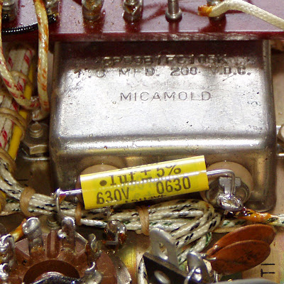
Fortunately the circuit is not very complex. There is one capacitor that can be changed to adjust the time constant for the limiter circuit. It's a 1.0 uF Micamold cap. It's the the huge shiny silver box shown below:

It's C1 in the schematic (click on the schematic for a larger version):

I removed the lead form the left hand terminal of the original cap and used that lead to connect a new cap from the tube cathode pin to the base of the cathode resistor. It actually physically connected to the other terminal of the original cap, but that made a more convenient connection point. With the other lead disconnected the cap is out of circuit so there's no reason not to.

We tried a few different values in studio to hear what sounded best and ended up with 1/10th of the original value. That's the one you see in the circuit now. It's a Mallory 150 series .1 uF cap. Now the unit sounds great and is operating at normal levels. While I was there a shot pictures of the entire manual. If there's anyone looking for a copy, email me and I'll send it along as a PDF.


2 comments:
Cool article you got here. I'd like to read a bit more about this theme.
BTW check the design I've made myself Young escort
This iis awesome
Post a Comment