In the last post we left off with three points whose combination of current and voltage fell along the load line:

This whole load line business gets a bit abstract and that can make it hard to think about it in terms of the actual circuit. To try to bring it back to earth a bit (or at least back to the schematic) here's a picture illustrating where that plate voltage appears in the circuit*:

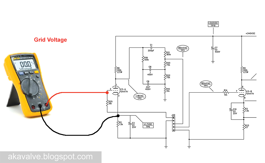
If you were to connect your meter's red and black leads to the points indicated in the schematic the voltage you'd be reading on the meter would be the voltage that appears on the X axis of the plate curves graph we've been working with. We'll see later that this voltages changes a great deal depending on the bias point and the nature of the signal that is connected to the input. The fact that this voltage changes according to the input is exactly what makes the tube function as an amplifier.
Move the red lead to the other side of the plate resistor and you'd be reading the B+ voltage. This voltage should remain pretty much constant with signal applied or without:

Now move both leads and you'll be reading the grid voltage:

The grid voltage is indicated on the plate curves as well. Here is the graph with the load line again. Have a look at the top end of the curves - you'll see a voltage label on each of them:
 By following the grid voltage curve to it's intersection with the load line, you can see what grid voltage (-0.5 volts) that corresponds to the plate voltage and current we've chosen at point A:
Since the grid voltage curves are pretty widely space you have to guesstimate when the points on the load line fall in between curves. I've done that here for points B and C.

Using these points and the three values associated with each of them we can calculate the value of the cathode resistor in order to set the bias. We can also use them to calculate the gain of the stage. We'll do that in the next post.
* This is the plate voltage relative to ground. There are times when you need to measure the plate voltage relative to the cathode but this measurement will work fine for what we're concerned with here.


2 comments:
Excellent job!
I'd rather call that third measurement a Grid-Katode voltage. But otherwise the whole series Fender Champion 600 is very nice.
I have a silly question, what is the ohm of R15 and R16?
Post a Comment