Sunday, December 28, 2008

Fender Champion 600 12DW7 / ECC832 Mod Part 2


Here's a look at the 12DW7 / ECC832 tube I used in the Champion 600 12DW7 Mod Part 1 .

Starting with the pin out diagram:


You can see from the diagram that, like other 12A*7 tubes, the 12DW7 has two triodes. Each triode has three connections - pins 1,2,3 and 6,7,8 respectively.

On most 12A*7 tubes (12AX7, 12AT7, 12AY7, 12AV7, 12AU7) the two triodes
in a single tube have identical characteristics.

In a 12DW7 the two triodes are different.

The section listed as Section 1 on the data sheet uses pins 6,7 and 8 and has characteristics identical to one half of a 12AX7.

The one listed as Section 2 uses pins 1,2 and 3. This section is identical to one half of the lower gain 12AU7 .

As an illustration, here's a Traynor YB1A with a 12DW7 in the first valve position:


Input 1 feeds the 12AU7 half of triode and input 2 feeds the 12AX7 half. The input is about 120 mV RMS and the meters are reading the output voltage from each of the two triodes.

The left hand meter reads 6.3 V for the 12AX7 stage output - that's a gain of 53 (6.3 V output/120 mV input).

The right hand meter reads 1.6 V for the 12AU7 stage output - that's a gain of 13 (1.6 V output /120 mV input).

So you can see the most obvious difference when swapping a 12DW7 for a 12AX7 is going to be a lower overall stage gain with the 12DW7.

This is also apparent if you look at the Amplification Factor in the data sheet (highlighted in yellow).


Amplification Factor
is related to the gain of the stage the triode is used in. It should not be thought of as the actual gain of a stage - it is actually the maximum possible gain in a stage designed to use that triode. As you can see in the measurements in the YB1A above, the actual stage gain for the 12AX7 was just above 50, even though the Amplification Factor for a 12AX7 is 100. The reasons for this are too complicated to get into here, but I'll post them independently at a later date. Suffice it to show that the 12AU7 stage has a significantly lower gain than the 12AX7 one (the combined gain for the two stages will be roughly the same as if you substituted a 12AY7 for the 12AX7).


The second and slightly more subtle difference is evidenced in what is listed as the Grid Voltage (highlighted in blue). Doubling this number will give a very rough sense of the possible input headroom available to the stage. It a very inexact number but good enough for the sake of illustration.

For Section 1 then the input headroom would be 4 volts. For Section 2 it would be 17 volts. A typical 12AX7 stage can output over 4 volts with an input of only 70 millivolts. At 120 millivolts it easily clears 6 volts:


Many guitars can output over 500 millivolts. And those voltages are in RMS - the peak to peak voltage is 2.828 times the RMS voltage (peak to peak voltage is what you really have to look at if you're concerned with the headroom of a stage).

So you can easily see that if the second stage is also a 12AX7 triode and there is no attenuation between stages, the second stage is going to be clipped. A 12AU7 has 4 times the input headroom of a 12AX7 (even more if it's run into the nonlinear part of it's curves). So using a 12AU7 as a second stage has some advantage if you're looking to keep things clean.

Plugging a 12DW7 into a Champion 600 actually places the 12AU7 section before the 12AX7 section, which is why the first stage is the one I rebiased in Part 1 of this posting.

Tuesday, December 23, 2008

Spring Clip Tube Removal Tool


Tight spring clips do a good job of keeping your power tubes in place. They can be a pain when you're trying to get the tubes out though - especially when the amp is still is it's cab and you're trying to wrestle two hands around a hefty output transformer. Here's a tool I came up with to make the job a bit easier.


Fender Champion 600 Output Transformer


Another difference between the new Fender Champion 600 and the older Fender Champ 5E1 and 5F1 circuits is the higher supply voltage (also called the B+ voltage) and an accompanying higher impedance primary on the output transformer in the Champion 600. I've never measured an original myself but replacements like the TF103-48 have a 5K ohms primary impedance. My measurement for the Champion 600 transformer at 1kHz is about 11K ohms.

I was a bit surprised by this so I called Mercury Magnetics to ask them about the impedance of the output transformer in their C600 Champion Upgrade Kit. They said their measurement was around 9K for the original and that they raised it a bit to 10K for the upgrade.

I don't have the details for their measurement, but here's the details of mine:


The tone generator (center) is set to input 1 volt @ 10Khz into the secondary of the output transformer (shown on the left side meter). The right hand meter shows the voltage output on the primary with 1 volt on the secondary. So here's how the primary load is calculated.

A transformer impedance ratio is equal to the square of it's voltage ratio.
Here the voltage primary to voltage secondary is 59.4:1
59.4 squared is 3,528
So for a 1 ohm load, the load reflected at the primary would be 3,528 ohms.
But the Champion 600 doesn't have a 1 ohm speaker for the load, it's 4 ohms.
That will raise the the impedance reflected at the primary 4 times.
So 3,528 times 4 is 14,112 or about 14k ohms.

But didn't I say I measured about 11K?

Yes - but at 1kHz. The above measurement was for 10Khz.
Transformers (especially cheap ones) are imperfect devices and their response varies with frequency.

Below is the same procedure, but at 1k.


With 1 volt on the secondary at 1 kHz, the reading on the primary is 52.94 volts (rounded to 53).

Here the voltage primary to voltage secondary is 53:1
59.4 squared is 2,809
So for a 1 ohm load, the load reflected at the primary would be 2,809 ohms.
So 2,809 times 4 is 11,236 or about 11k ohms.


Here's the reading at 100Hz:


With 1 volt on the secondary at 100 Hz, the reading on the primary is 44 volts.

Here the voltage primary to voltage secondary is 53:1
44 squared is 1,936
So for a 1 ohm load, the load reflected at the primary would be 1,936 ohms.
So 1,936 times 4 is 7,744 or about 8k ohms.


From this you can see that if you load the 4 ohm secondary of a TF103-48 with a 8 ohm speaker you raise the primary load to 10k - same as the Mercury Magnetics. Of course there's a whole lot more to a transformer than just the loading, but if you need to replace the OPT in a Champion 600 and are short on dough an 8 ohm speaker on the 4 ohm tap should get you back in business.


UPDATE: For comparison, I've posted measurements for an AB764 Vibro Champ output transformer here.

Float Your Screen Resistors!


Here's a pretty extreme example of what happens when you
screen resistors are too close to the pc board. This is why it's important
to "float" higher power resistors off the circuit board.


The amp here is an Ampeg V4B. The board was so burned that the
screen resistors were moved off to the power tube sockets.
The resistors that burned up were replacements,
the originals would have been underneath the pc board.

In the center of the picture below is a floated resistor in a
Fender Champion 600. The breathing room beneath
the resistor reduces the chance of the pc board being
damaged if the resistor overheats or flames out.


It's shocking that some new production amps don't bother
to do this as their pc boards are generally very delicate.
There is no really effective way to repair a pc board
once it goes. Your tech can kludge in jumper wires
but the amp will never be "like new".


Fender Champion 600 12DW7/ECC832 Mod Part 1


This post has been
updated.

I'll leave this old page in place until I've checked all the links.


Sunday, December 21, 2008

Fender Champ - comparing the 5F1 and 5E1 circuits


Fender Champ 5F1 and 5E1 schematic comparison


In modding their Champion 600's, some people are trying to get closer to earlier versions of the Fender Champ circuit, the 5E1 and 5F1. This post is to clarify the differences between those two early circuits. There are two significant ones.

The first is the missing cathode bypass capacitor in the 5F1. Eliminating this cap reduces the first stage gain. Reducing the value instead of eliminating it completely will give a bit of a treble boost (see my earlier post "Champion 600 cathode bypass mod" for a chart showing how different capacitor values will effect the response).


Secondly, in the 5F1 champ the choke has been eliminated and a screen supply node consisting of a capacitor and resistor has been added. This saved Fender some cash, as a choke is a good bit more expensive than a cap and a resistor. In a Class A amp a choke doesn't contribute to sag they way it does in a Class AB amp, but the change still has an effect. The screen supply resistor in the 5F1 drops the voltage for the screen below that of the plate. Since the screen voltage actually has more effect on plate current than plate voltage, this changes the character of the output section. If you really want to hear if the choke makes a difference between the two circuits you need to put the choke in series with the screen supply resistor, not eliminate the resistor completely.


Wednesday, December 17, 2008

Fender Champion 600 cathode bypass mod


This post is from the series of mods I've done to this Champion 600. I'm finally getting down to changing the circuit a bit. My main goal is to clean the amp up a bit, especially in the low end. It's probably going to require a speaker replacement eventually, but I'm starting with the cathode bypass caps.

With most 12AX7 circuits, smaller bypass cap values will reduce the low end response by a bit less than 6dB. The frequency at which the response is down by 3dB is, logically, the "3dB down point" or the "knee frequency". Changing cathode bypass caps can be a bit more subtle than changing coupling caps since the low end response is never reduced more than 6dB - only the knee frequency is changed.

There are two cathode bypass caps in the preamp section of the Champion 600. Either or both of them can be changed out to shape the frequency response of the amp.

Here they're indicated on the pc board layout - C3 is for the first stage and C10 is for the second:


Modding the Fender Champion 600 - cathode bypass caps


A standard tuned 6 string guitar isn't going to produce anything below 80Hz and even the low frequencies it does produce aren't going to reproduce well though the Champion 600's speaker. Below is a chart with values calculated for the 3dB down point with a series of common cap values. Note the stock value of 22uF has a -3dB point of 9Hz. I'm going to start with a 1.5uF in the first stage and a .68uF in the second and work from there.

If electrolytic caps are used (and they probably will be for the larger values unless you've got deep pockets) it's very important to maintain the polarity of the cap or it will explode under use.


Modding the Fender Champion 600 - cathode bypass capacitor value chart

This amp came to me with a printed copy of the Frondelli Mod . The mod itself is fine, but a number of the changes detailed there do the opposite of what this amp owner is looking for. He's looking for a cleaner sound with more low end headroom. Even though Frondelli is limiting the low end somewhat, he is also increasing gain for a more saturated sound. If that's what you're interested in, though, you can tweak the bypass cap value to your taste there as well. The blue resistors in the diagram below indicate the ones changed for the 1st stage in the Frondelli mod (R8 and R2). The bypass cap associated with that stage (C3) is indicated in orange.

Modding the Fender Champion 600 - Frondelli Mods parts location
Jon Frondelli recommends a .68 uF cap here, but you're free to change it to taste. Below is a chart showing calculated -3dB values adjusted for the new plate and cathode resistor values in the Frondelli mod.


Modding the Fender Champion 600 - Frondelli Mod cathode bypass cap value chart
If you're interested in how these values are calculated, drop me an email - or visit Randall Aiken's site.

Tuesday, December 16, 2008

Inside the Fender Champion 600


There are a few relatively pleasant surprises inside the Champion 600.
Granted, the bar is pretty low for current production budget amps,
but here's a few things I was glad to see.


Fender Champion 600 mod power resistor

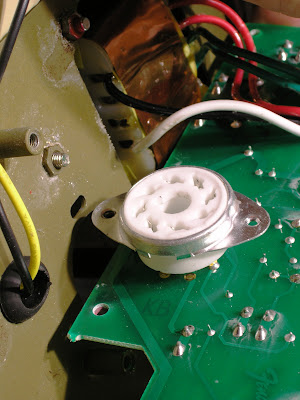
The 3 higher power resistors are all floated well off the circuit board
(one of them is shown in the middle above).
This allows them to dissipate heat more effectively and keeps them
from cooking the pc board when they get hot.


Modding the Fender Champion 600 - 6V6 octal socket
Even though the octal socket for the 6V6 is mounted to the pc board, the socket also screws to the chassis when the amp is fully assembled. When it's screwed down it has a pretty decent mechanical connection. Not perfect, but better than average for today's amps.

There are plenty of amps in which the only mechanical support for the tube socket is the solder that makes the electrical connections for the tube pins. These inevitably get strained when tubes are taken in out. Usually they cause an annoying intermittent failure long before they crap out completely.


Modding the Fender Champion 600 - 12AX7 preamp socket

The 9 pin preamp tube socket isn't quite as good but better than a lot I've seen. It's mounted directly to the board with no independent mechanical support. The top ring on the socket fits pretty snugly into the hole in the chassis. The pc board mounting screws are close enough to the socket that the board doesn't flex too much when the tube is wiggled out of place.


Modding the Fender Champion 600 - input jacks volume pot

The plastic jacks are better than I expected them to be. And the way the small front panel circuit board is implemented it would be easy to eliminate the card completely and replace the jacks and the volume pot with more robust components. There's also plenty of real estate immediately available for switches and such - both under the chassis and on the front panel. I'm planning to have a few switches in there, at least for the testing phase, so it's nice to have the space.


Monday, December 15, 2008

Disconnecting PC Board Spade Connectors


PC board spade connectors can be difficult to pull off gently.
Here's how I do it when there's enough room to get pliers in there.
The board here is from a Fender Champion 600.


Opening a Fender Champion 600 for modding


opening the Fender Champion 600 for modding


Getting ready to make some circuit changes to this little Champion 600.
The gif is just for fun really.
If anyone is interested in more detail let me know.
I have photos in much higher res.


Saturday, December 13, 2008

Fender Champion 600 vs Epiphone Valve Junior


Here's a frequency plot of a stock Epiphone Valve JR and a stock Champion 600, each using the Eminence Legend 12" speaker in a Fender Deluxe Cab.

Notice the relative low frequency roll off and the 725 HZ bump on the Valve Junior plot.

What's not evident here is that the gain setting on the Champion 600 is at about 12:00 the gain on the Valve Junior is about 9:00 for the same output.


Fender Champion 600 Part 1


Fender Champion 600 speaker responseFender Champion 600 with Ampeg Jet Alnico speaker responseFender Champion 600 with Deluxe Reverb speaker responseFender Champion 600 with Celestion Century speaker response


Below is a frequency plot for a Fender Champion 600 using it's own speaker first, then with the internal speaker unhooked and the Champion amp connected directly to the speaker in 4 different combos.


Stock Champion 600 Ampeg Alnico Eminence Legend Celestion G12 Century speaker response

Green is the stock speaker

Purple is the stock alnico in and Ampeg Jet Cab

Red is an Eminence Legend 12" in Fender Deluxe Cab

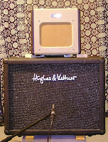
Yellow is a Celestion G12 Century in a Hughes & Kettner Puretone Cab


Three things strike me about the stock speaker plot:
• The 90Hz low frequency resonance of the speaker is quite strong.
• The high frequency response is extended above 5KHz.
• The speaker sensitivity is the lowest of all of the four tested.

The low frequency bump on the is certainly not helping the muddiness or lack of low end headroom that characterize the Champion. The next step will be to modify the circuit to limit the low frequency response.

Tuesday, December 9, 2008

Fender Pro Junior Cathode Bias Mod


Fender Pro Junior Stock
I got this little Pro Junior in trade a while back. These things sound pretty decent even stock. This one was cutting out intermittently though. Turns a few solder joints were cracked where the sockets were mounted on the PC board (pretty common with board mounted sockets). The board itself was OK so the fix was quick and easy.

Here it is with the back off:


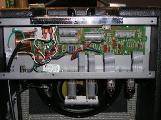
Fender Pro Junior Mod Inside

When I looked over the main circuit board, I noticed that the wire marked W1 was a jumper to ground for the power tube cathodes. That would make for a quick and easy modification to cathode bias. So I figured I had it open, why not. And if I'm going to bother, why not make it switchable fixed/cathode bias.

Fender Pro Junior Cathode Bias Switch
THE UBIQUITOUS DISCLAIMER: AKAVALVE ASSUMES NO RESPONSIBILITY FOR THE SAFETY OF ANYONE IMPLEMENTING THESE INSTRUCTIONS. IF YOU ARE NOT FAMILIAR WITH SAFE PRACTICE IN HIGH VOLTAGE CIRCUITS, DO NOT ATTEMPT THIS YOURSELF.

Here's the 22oK resistor assembly. They'll serve as the bias feed resistors in fixed bias mode and as ground reference for the power tube grids in cathode bias.

Fender Pro Junior Cathode Bias Mod 220K Ground Reference Resistors

I futzed a bit with the cathode resistor value. I was planning on selling this amp, so I ran it slightly on the cool side so that whoever ended up with it wouldn't have a tube eater on their hands. Here's the final assembly.

Fender Pro Junior Cathode Bias Mod

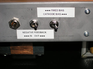
The black wires run off to the right hand switch. You can see I also added a switchable
negative feedback loop. It was a bit inconvenient having the switches under the chassis but I didn't want to change the faceplate and it was a much shorter run for the wiring.

Fender Pro Junior Cathode Bias Mod Switches


When I was done the amp sounded pretty cool. The pair of switches made it a good bit more versatile. In cathode bias with the feedback loop disengaged it was much looser, browner and more touch responsive - a much better blues sound. Engaging the feedback loop and or the fixed bias would make it tighter, cleaner and brighter.

I sold this particular one awhile back so I can't get more photos. I think my Dad still has a stock one though. If anyone's interested in a more detailed procedure, drop me a line - he might be convinced to let me use it for a step by step demo.

Monday, December 8, 2008

The Tube Amp Book by Aspen Pittman


The Tube Amp Book by Aspen Pittman review


The Tube Amp Book has always been a sort of infomercial for Groove Tubes. I've never had much use for the first half it - glossy photos of classic guitar gear and a catalog of Groove Tubes product line. The second half though is a good source of schematics - which is what I've always valued it for. My old copy of Volume 3 is broken in half and shedding pages from the split. I got the Deluxe Revised Edition for Christmas last year and what I love about it is that it's spiral bound so it lies flat without breaking the spine.

Here's the old and the new:


The Tube Amp Book by Aspen Pittman Deluxe Review

The schematics are also printed a bit larger (the book is much bigger but now there are two schematics per page). This is what's left of my Volume 3 - I'm missing a few pages of Fender Champ schematics:

The Tube Amp Book by Aspen Pittman Volume 3
The Deluxe Revised Edition actually has fewer printed schematics than the older editions. It's down to 368 from 408 in the past. Ampeg V4's seem a lot more common to me than some of the others they chose to include. Maybe it's a Boston thing. It's conspicuously missing from the new edition though. It is still on the included CD of schematics. There are 800 on there. It's not as useful as the printed ones, but it's still handy if you don't have a web connection near your bench.

The Deluxe Revised Edition also has a slightly expanded technical section. It's a bit random and only slightly useful IMHO but now includes an article on Class A by one of my favorite technical writers Randall Aiken. There's some tube data there too, which is handy to have around but it doesn't have curves for all the tubes listed which is a disappointment. Like schematics, tube data is easy to find elsewhere - the Tube Data Sheet Locator at Duncan Amps is one good hub.

Before schematics were widely available electronically, TTAB had a bit of a corner on the market. Now, since all of the schematics in are easily found at such places as Schematic Heaven, TTAB has taken some shots for selling material that anyone get for free on the web. As I see it you're really paying for the printing, binding and organization. To me, it's worth the $35 or so cover price to bypass the downloading, printing, punching and binding of 350+ schematics. Sure, not everything you're looking for is in there but it's a handy reference for most amps you're likely to run into.

Sunday, December 7, 2008

Ampeg V4 curiousities part 2


This is a look a some of the less common tubes used in the preamp section of the V4. There's also a view of the circuit board revealing one of the major differences between the V4 and the V4B.


Saturday, December 6, 2008

Ampeg V4 curiousities part 1


A quick tour of the power supply end of the underside of the circuit board and a look at the unusual plate resistors.


Friday, December 5, 2008

Adjustable Bias for an Ampeg V4B


Ampeg V4 V4B adjustable fixed bias mod


This is a shot from an Ampeg V4B that's currently in for repairs. It blew the flyback protection diodes and then shorted a power tube. I thought it would be better off not biased quite as cold as these V series amps are stock.

The change is pretty simple - I replaced R49 (a 75k resistor) with a 47K resistor in series with a 20 turn 25K cerment pot. The wiper of the resistor is connected to the supply diode and one leg is attached to the 47K resistor. The other leg of the pot is unused. A dab of silicone under the pot holds it in place and keeps adjustments from stressing the leads or the solder joints. It gets the bias voltage down as low as about -40 volts. Stock its about -60 volts. The nice thing about this arrangement is that if the pot were to fail with an open circuit on the wiper the bias voltage would actually go up and the tubes would be protected.


carbon comp v.s. metal film resisitors


This is another test post of sorts - seeing how well the video works.

The videos show a comparison of the heat stability of metal film resistors compared to the traditional carbon comp ones.

After watching the video, imagine what those carbon comp screen resistors hanging over the top of the tube socket of your old Fender are doing as your amp heats up. They aren't going to get as hot as they do when hit with the heat gun. But if you imagine all the carbon comps in your amp drifting a bit with heat you can imagine the amp's not going to sound the same. Might be better might be worse but it won't be consistent.

Here's the IRC metal film one:


And the carbon comp:


Thursday, December 4, 2008

Ampeg V4B bias mod


A bit of a test post really - trying out the photo upload.

This is the inside of a Ampeg V4B that had burned out the screen resistors. The pic shows a mod done I found in there done by a previous tech. Stock V series amps derive the bias from the B+ supply. The transformer next to the power tubes was added across the heater supply to kludge an independent bias supply winding in the power supply.

getting started

When I was starting to learn about electronics, finding good introductory tube circuit material was no small task itself. There were plenty of old EE texts but that's a tough place to start if advanced math is not you idea of a relaxing Saturday morning. There were also a smattering of "guru" sorts of books but they were more collections of tips and trivia than solid technical introductions. Nowadays tube info on the web is so ubiquitous that the veteran RCA Tube Manual seems awkward and incomplete and many of the old gurus serve as punching bags for website FAQ's. Actually learning the ropes isn't all that much easier though. First there's sorting out the bogus information. That's a bit of catch 22. You need a certain level of understanding to work through it and if you have that understanding then chances are you already have that information. Then there's struggling with the fundamentals of electronics and the peculiarities of vacuum tubes. That's a study that never ends but it can be particularly difficult to get rolling. This blog'll be sort of an offhand collection of work that passes over my bench along with bits of "tube amp basics" for people trying to get through the fundamentals and onto the fun stuff. Hope you enjoy it.